Piloted exhaust line valve and corresponding production method

a technology of exhaust line valve and production method, which is applied in the direction of lift valve, functional valve type, exhaust gas recirculation, etc., can solve the problem of relative high cost and achieve the effect of reducing the number of parts making up the valve, reducing the manufacturing cost of the valve and simplifying the design of the valv

Active Publication Date: 2019-10-24
FAURECIA SYST DECHAPPEMENT
View PDF5 Cites 2 Cited by
  • Summary
  • Abstract
  • Description
  • Claims
  • Application Information

AI Technical Summary

Benefits of technology

[0012]Thus, it is not necessary to provide, in the valve body or on another valve component, a stop specifically designed to lock the first tube in position during assembly of the valve, when the first tube is engaged inside the valve body. This stop is achieved by using the guide bearing. The guide bearing thus allows the first tube to be held in its nominal position until the tube is fixed to the valve body.
[0013]The design of the valve is therefore simplified, and the number of parts making up the valve is reduced. As a result, the manufacturing cost of the valve is also reduced.

Problems solved by technology

Exhaust systems for entry-level vehicles do not include such valves, due to their relatively high cost.

Method used


Image

  • Piloted exhaust line valve and corresponding production method
  • Piloted exhaust line valve and corresponding production method
  • Piloted exhaust line valve and corresponding production method

Examples


Embodiment Construction

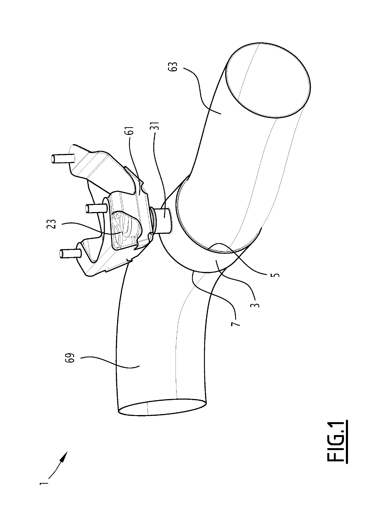
[0038]The valve 1 shown in FIGS. 1 to 3 is intended for installation in an exhaust system of an internal combustion engine vehicle. This vehicle is typically a motor vehicle such as a car or truck.

[0039]The valve 1 is designed, for example, to vary the cross-section of the exhaust gas passage in an exhaust system component, such as a tube or silencer, to modulate the amount of recirculated exhaust gas at the intake of the internal combustion engine (EGR, Exhaust Gas Recycling), or to divert all or part of the exhaust gas flow to a heat exchanger or bypass duct of an exhaust gas purification device such as a NOx trap or SCR (Selective Catalytic Reduction) catalyst.

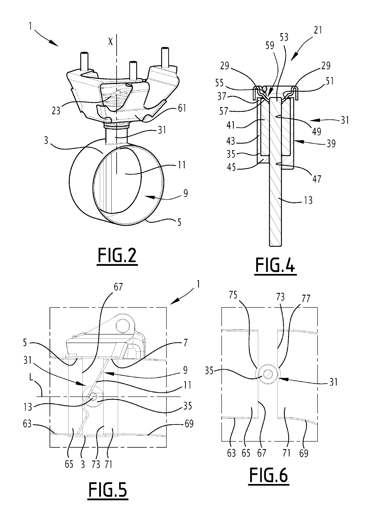
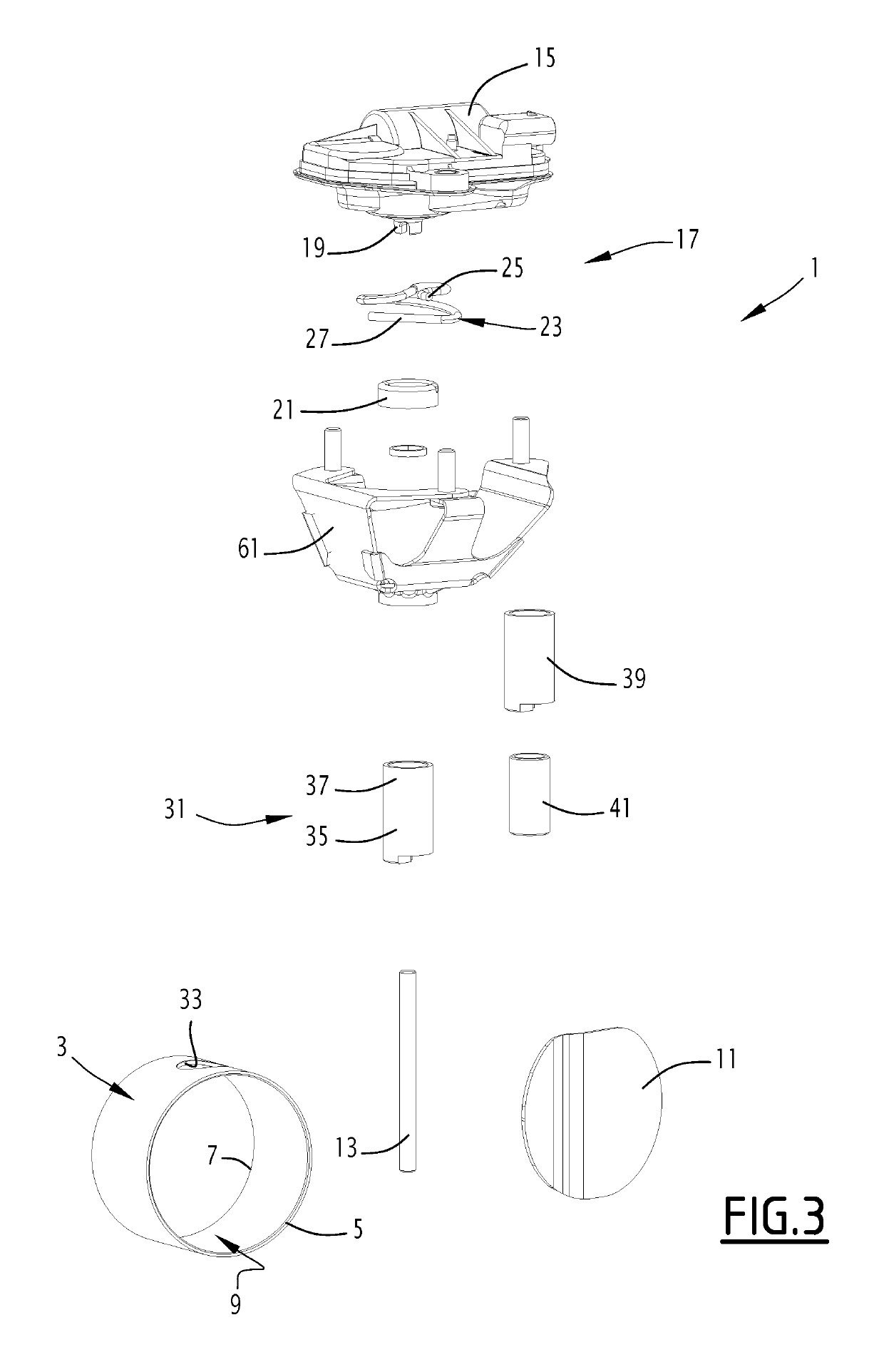
[0040]The valve 1 has a valve body 3 with an exhaust gas inlet 5 and an exhaust gas outlet 7.

[0041]The valve body 3 defines an exhaust gas circulation passage 9 between the exhaust gas inlet 5 and the exhaust gas outlet 7. In the example shown, the valve body 3 is a pipe section with a circular cross-section. Alternatively,...


PUM


Abstract

A valve includes a valve body having an exhaust gas inlet and an exhaust gas outlet, the valve body defining an exhaust gas circulation passage between the exhaust gas inlet and the exhaust gas outlet. A flap is arranged in the valve body and a shaft drives the flap in rotation with respect to the valve body. At least one guide bearing guides the drive shaft of the flap for rotation relative to the valve body. The guide bearing is engaged through an orifice of the valve body, with an inner end of the guide bearing being located inside the valve body. A first tube is engaged in one of the exhaust gas inlet and exhaust gas outlet and abuts against the inner end of the guide bearing.

Description

CROSS-REFERENCE TO RELATED APPLICATIONS[0001]This application is a U.S. non-provisional application claiming the benefit of French Patent Application No. 18 53582, filed on Apr. 24, 2018, which is incorporated herein by its entirety.FIELD OF INVENTION[0002]The invention generally concerns controlled valves for exhaust systems.BACKGROUND OF THE INVENTION[0003]Such piloted valves are normally installed in the exhaust systems of high-end motor vehicles. Exhaust systems for entry-level vehicles do not include such valves, due to their relatively high cost.[0004]In the near future, new standards will be introduced to limit the noise emissions from vehicle exhaust systems even more severely. These standards will force car manufacturers to make widespread use of pilot operated valves, which are a technical solution to reduce noise emissions.[0005]In this context, the invention aims to offer a valve whose manufacturing cost is reduced, and which can therefore be used on all kinds of exhaust...

Claims


Application Information

Patent Timeline
Patent Type & Authority Applications(United States)
IPC IPC(8): F16K1/22F16K15/02F02M26/66F01N1/16F01N1/18
CPCF16K1/225F16K27/0218F16K15/023F02M26/66F01N1/166F01N1/18F02D9/04F02D9/104F02D9/106F16K1/2268F02M26/70F01N1/163F16K1/22
Inventor BOTELLA, RONANCAMBILLARD, JULIENHALEPOVIC, ALEN
Owner FAURECIA SYST DECHAPPEMENT
Why Eureka
Try Eureka