Valve system for internal combustion engine

a valve system and internal combustion engine technology, applied in the direction of valve details, valve arrangements, valve drives, etc., can solve the problems of high cost of coil springs and difficulty in accurately transmitting motion from the control lever to the frame, and achieve the effect of preventing the spring from falling off, reducing the cost of the valve system, and low cos

Inactive Publication Date: 2006-02-21
HONDA MOTOR CO LTD
View PDF6 Cites 2 Cited by
  • Summary
  • Abstract
  • Description
  • Claims
  • Application Information

AI Technical Summary

Benefits of technology

[0009]According to this, the holder side connection portion is normally pressed against the control mechanism side connection portion in the swinging direction by the pressing energizing means, whereby the influence of the play between both the connection portions is eliminated, and, when the control mechanism and the holder are put into relative motions for controlling the valve operation characteristics, both the members are maintained in the condition of making contact with each other in the swinging direction at their connection portions, so that the motion of the control mechanism is accurately transmitted to the holder.
[0022]Since the control spring is composed of a straight hollow cylindrical spring which is inexpensive, the cost of the valve system is reduced. In addition, since the straight hollow cylindrical control spring is prevented, by the spring guides inserted into the inside of the control spring at both end portions of the latter, from being disengaged from the spring holding portions, the control spring is assuredly held by the spring holding portions. Moreover, since the control spring is prevented from making contact with the spring guides even when curved into an arcuate shape, durability of the control spring is enhanced.

Problems solved by technology

The presence of the play, however, makes it difficult to accurately transmit a motion from the control lever to the frame.
However, the coil spring is a special spring which is curved in an arcuate shape, so that the coil spring is high in cost.

Method used


Image

  • Valve system for internal combustion engine
  • Valve system for internal combustion engine
  • Valve system for internal combustion engine

Examples


Embodiment Construction

[0040]Now, an embodiment of the present invention will be described below, referring to FIGS. 1 to 12.

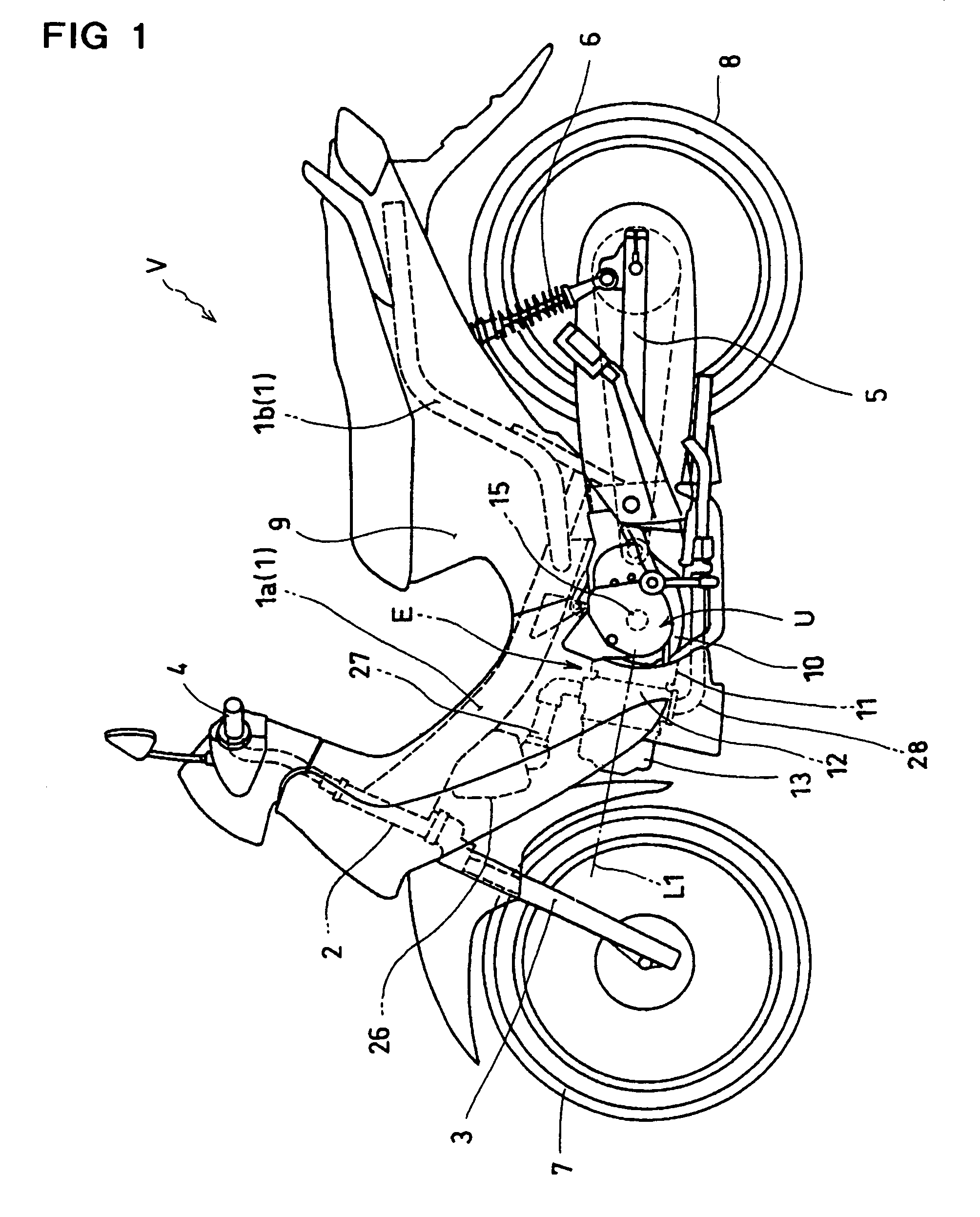
[0041]Referring to FIG. 1, an internal combustion engine E to which the present invention is applied is mounted on a motorcycle V representative of a vehicle. The motorcycle V comprises a vehicle body frame 1 having a front frame 1a and a rear frame 1b, a steering handle 4 fixed to an upper end portion of a front fork 3 rotatably supported on a head pipe 2 connected to the front end of the front frame 1a, a front wheel 7 rotatably supported on lower end portions of the front fork 3, a power unit U supported on the vehicle body frame 1, a rear wheel 8 rotatably supported on a rear end portion of a swing arm 5 swingably supported on the vehicle body frame 1, a rear cushion 6 for connection between the rear frame 1b and a rear portion of the swing arm 5, and a vehicle body cover 9 covering the vehicle body frame 1.

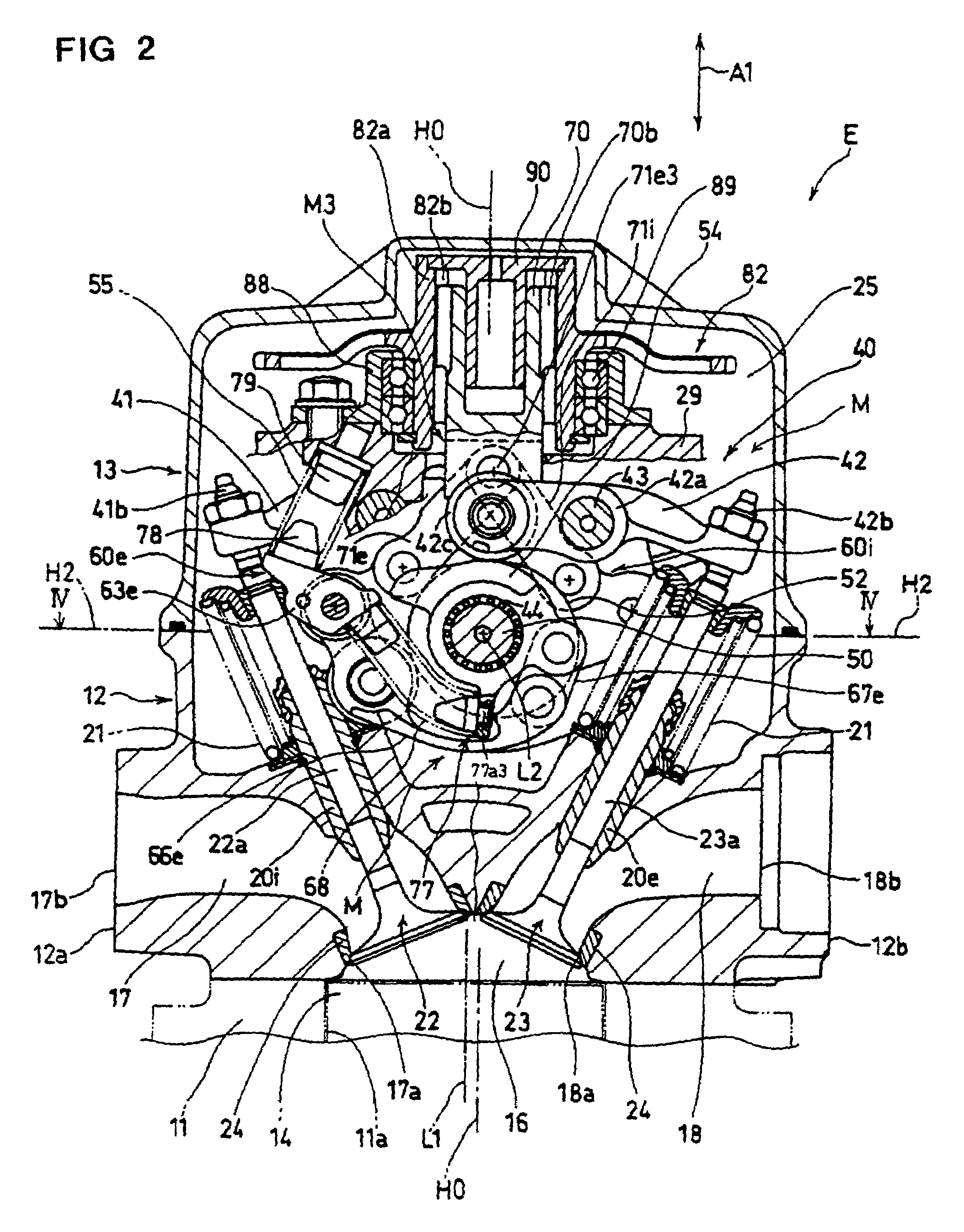
[0042]The power unit U comprises a transverse layout type internal combu...


PUM


Abstract

A valve system is provided to eliminate a play at connection portions in a valve characteristic varying mechanism and to enhance the accuracy in control of valve operation characteristics.

Description

FIELD OF THE INVENTION[0001]The present invention relates to a valve system for an internal combustion engine, and particularly to a valve system comprising a valve characteristic varying mechanism for controlling the valve operation characteristics of an engine valve composed of an intake valve or an exhaust valve.BACKGROUND OF THE INVENTION[0002]As a variable valve mechanism provided for an internal combustion engine and capable of changing the opening and closing timings and the maximum lift amount of an engine valve, there are, for example, those disclosed in U.S. Pat. No. 6,019,076 and U.S. Pat. No. 6,401,677 (B1).[0003]The variable valve mechanism disclosed in U.S. Pat. No. 6,019,076 comprises a swinging cam swingably supported on a camshaft for the purpose of opening and closing an intake valve or an exhaust valve, a control shaft driven by an actuator, a control lever having a drive pin and mounted to the control shaft, a control member which has a rocker lever for swinging ...

Claims


Application Information

Patent Timeline
Patent Type & Authority Patents(United States)
IPC IPC(8): F01L1/34F01L13/00
CPCF01L1/022F01L13/0015F01L13/0063F01L1/181F01L2820/032F01L2001/0535F01L2013/0073F01L2105/00F01L2305/00
Inventor INOMOTO, YUTAKAKUROKI, MASAHIROISHIKAWA, TOMOMI
Owner HONDA MOTOR CO LTD
Why Eureka
Try Eureka