

Encoding apparatus and method
a technology of encoder and encoder, applied in the field of image data encoder, can solve problems such as complicated decoding process, and achieve the effect of simplifying decoding process
- Summary
- Abstract
- Description
- Claims
- Application Information
AI Technical Summary
Benefits of technology
Problems solved by technology
Method used
Image

Examples
first exemplary embodiment
[0021]In the first exemplary embodiment, an arrangement and a processing procedure of an image coding apparatus will be described. The first exemplary embodiment may be applicable to any apparatus which includes a moving image data compression coding unit. For example, the first exemplary embodiment may be applied to an image capture apparatus represented by a video camera or digital camera, a mobile communication apparatus, or a computer.
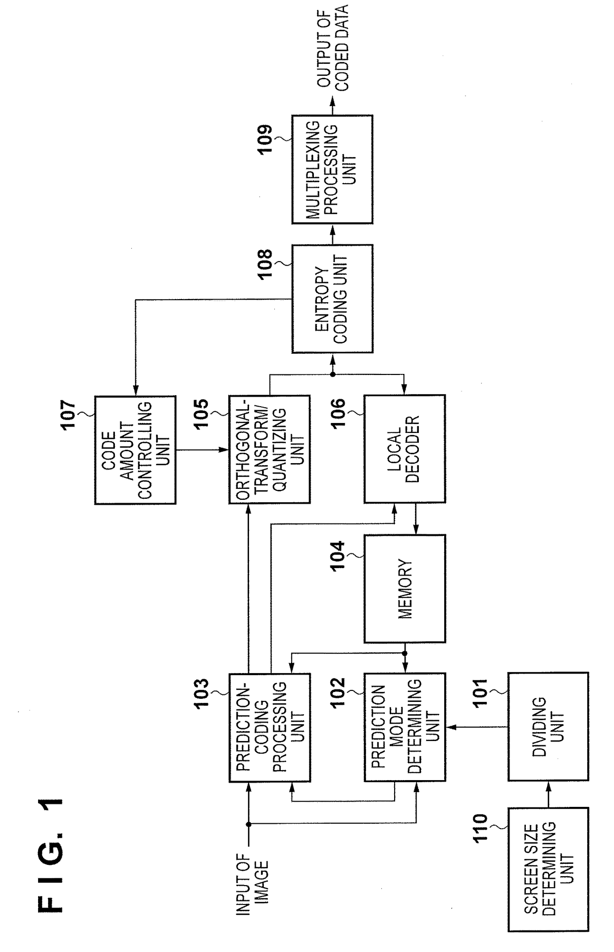
[0022]The arrangement and the processing procedure of an image coding apparatus for performing coding by an H.265 (ITU H.265 or ISO / IEC23008-2) method according to the first exemplary embodiment, will be described with reference to a block diagram shown in FIG. 1.
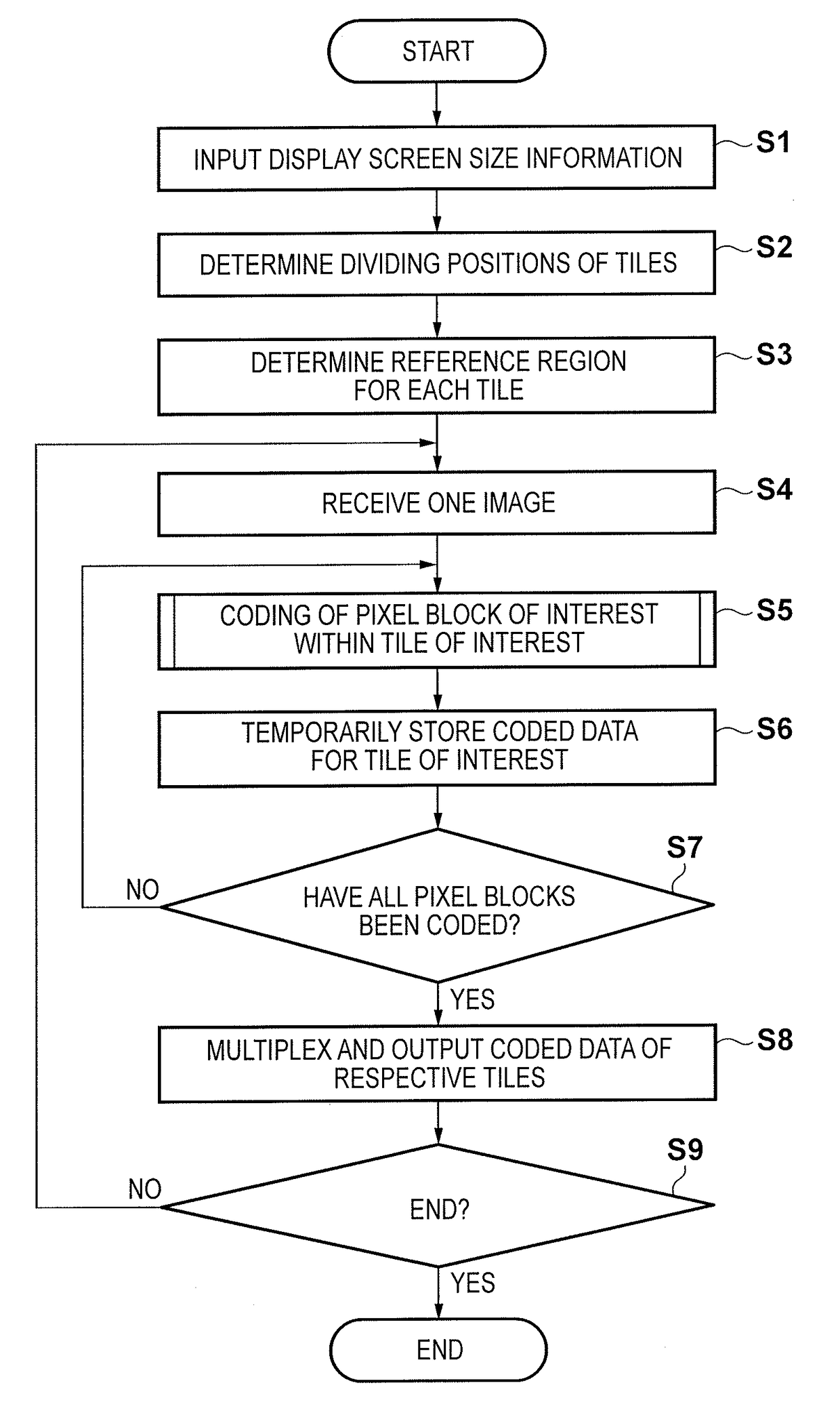
[0023]To conform to a size of a display screen on the decoding side, a dividing unit 101 first acquires, from a screen size determining unit 110, one or more display screen size information about one or more display screen sizes each smaller than an image size of a coding target input imag...
second exemplary embodiment
[0069]A region to be referred to when encoding one tile (a region where a prediction pixel block is derived) may be determined as follows.
[0070]When a tile of interest is a coding target tile, the range of a rectangular region including, at diagonal positions, the tile of interest and a tile which are point-symmetric with respect to the center position of a image to be coded is regarded as a reference region.
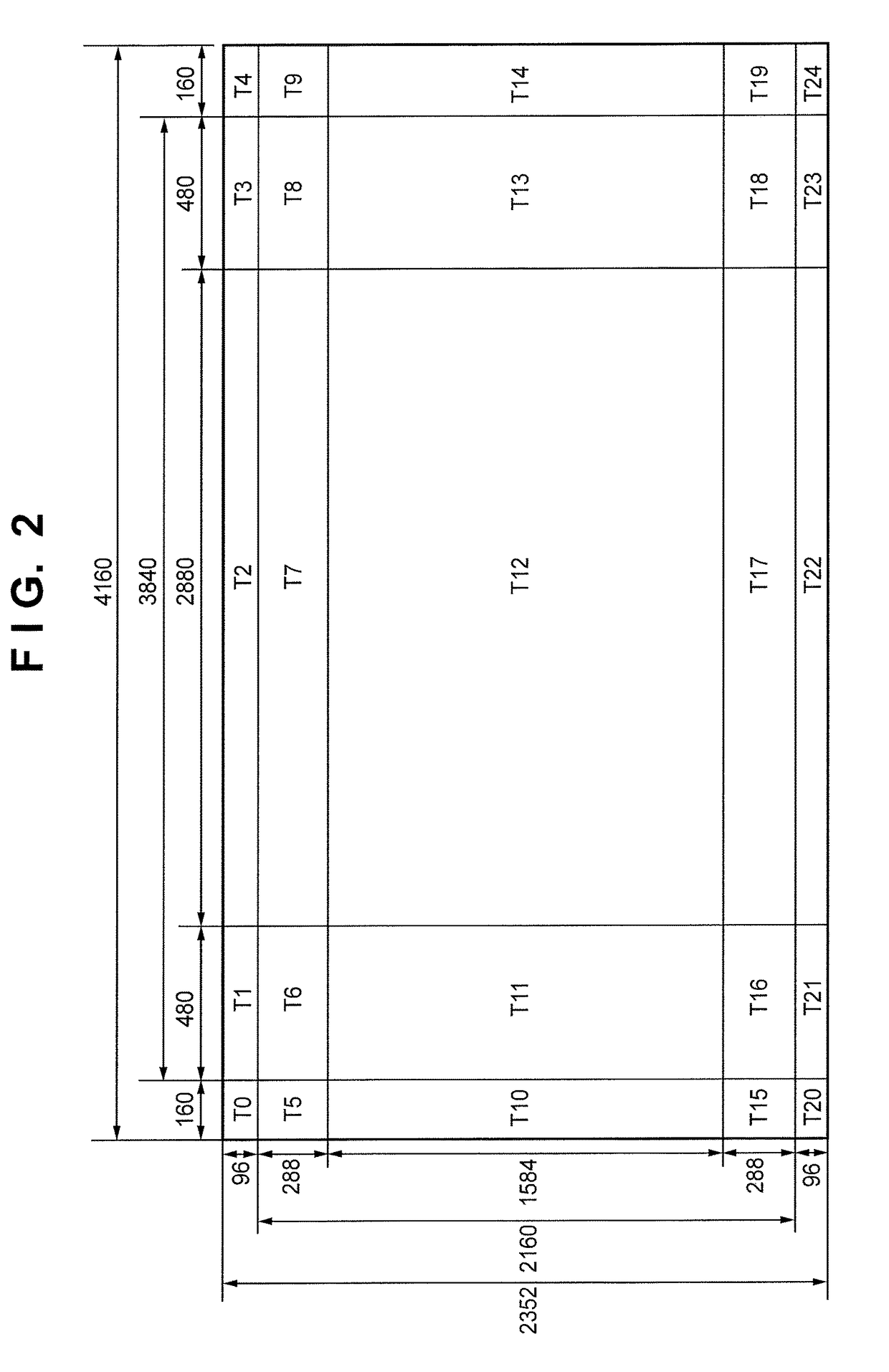
[0071]For example, focusing attention on a tile T0, a tile T24 is point-symmetric to the tile T0, as shown in FIG. 4A. Therefore, a rectangular region including the tiles T0 and T24 at diagonal positions, that is, the entire region is determined as a region to be referred to when encoding the tile 0. Focusing attention on a tile T6, a tile T18 is point-symmetric to the tile T6, as shown in FIG. 4B. Therefore, the range of tiles T6 to T8, T11 to T13, and T16 to T18 is determined as a reference region when encoding the tile T6. Furthermore, focusing attention on the tile T11, the ...
third exemplary embodiment
[0072]An arrangement and a processing procedure of an image coding apparatus for performing coding by the H.265 method according to the third exemplary embodiment, will be described with reference to a block diagram shown in FIG. 6. Components 501 to 509 shown in FIG. 6 are the same as the components 101 to 109 of the image coding apparatus described in the first exemplary embodiment and a description thereof will be omitted. A decoding auxiliary information generating unit 510 unique to FIG. 6 will be explained below.
[0073]In H.265, a network abstraction layer (NAL) is defined between an image coding layer (VCL) which handles image coding processing and an actual transmission / storage system. The NAL is packetized for each NAL unit made up of an NAL header and RBSP (Row Byte Sequence Payload). The NAL header can be used to identify the type of NAL unit, and the subsequent RBSP stores actual encoded data. The type of NAL unit mainly includes encoded image data (slice), SPS (Sequence ...
PUM
 Abstract
Description
Claims
Application Information