System and method to treat a multiphase stream

a multi-phase, fluid technology, applied in the direction of vortex flow apparatus, separation process, borehole/well accessories, etc., can solve the problems of difficult deep-water subsea separation, impracticality of vessel wall thickness to withstand water pressure, and difficulty in deep-water subsea separation, so as to enhance the separation of a denser substan

Active Publication Date: 2017-09-19
EXXONMOBIL UPSTREAM RES CO
View PDF22 Cites 11 Cited by
  • Summary
  • Abstract
  • Description
  • Claims
  • Application Information

AI Technical Summary

Benefits of technology

[0012]One embodiment of the present disclosure is a cyclonic coalescer for enhancing separation of a denser phase liquid from a lighter phase liquid within a multiphase stream, the coalescer comprising: a tubular housing; a plurality of coaxial flow chambers extending in the axial direction of the housing; and a swirling element associated with each of the plurality of coaxial flow chambers, the swirling elements are constructed and arranged to impart a tangential velocity of the stream flowing through the associated flow chamber.

Problems solved by technology

While subsea separation is not trivial is shallow waters (<1500 m), it becomes more challenging in deeper water.
At depths greater than 1500 m, the vessel wall thickness necessary to withstand the water pressure becomes impractical as the allowable vessel size is limited in diameter by wall thickness and weight.
As a result, deep-water subsea separation is a challenge since traditional large diameter separators cannot typically be used.
However, due to the size and weight constraints noted above, this is not practical for many offshore and subsea applications.
However, the availability of compact oil / water separation devices is limited.
Due to their polarized nature, the droplets are attracted and ultimately collide resulting in coalescence.
However, the high centrifugal acceleration causes the dense phase and / or light phase droplets to begin to shatter due to turbulent effects of the stream.
For this reason, application of cyclonic coalescers at practical scales outside of the lab environment has been challenged.
Known techniques fail to meet these challenges.
Due to the limited separation time in deepwater subsea separation and existing limitations of compact equipment, it is challenging to achieve separation of oil / water throughout the entire production life of the aforementioned fields without significantly reducing production rates during the inversion range, or accepting a lower quality oil / water separation from the subsea separation system as is normally achieved outside of the inversion range.

Method used


Image

  • System and method to treat a multiphase stream
  • System and method to treat a multiphase stream
  • System and method to treat a multiphase stream

Examples


Embodiment Construction

[0020]For the purpose of promoting an understanding of the principles of the invention, reference will now be made to the embodiments illustrated in the drawings and specific language will be used to describe the same. It will nevertheless be understood that no limitation of the scope of the invention is thereby intended. Any alterations and further modifications in the described embodiments, and any further applications of the principles of the invention as described herein are contemplated as would normally occur to one skilled in the art to which the invention relates. One embodiment of the invention is shown in great detail, although it will be apparent to those skilled in the relevant art that some features that are not relevant to the present invention may not be shown for the sake of clarity.

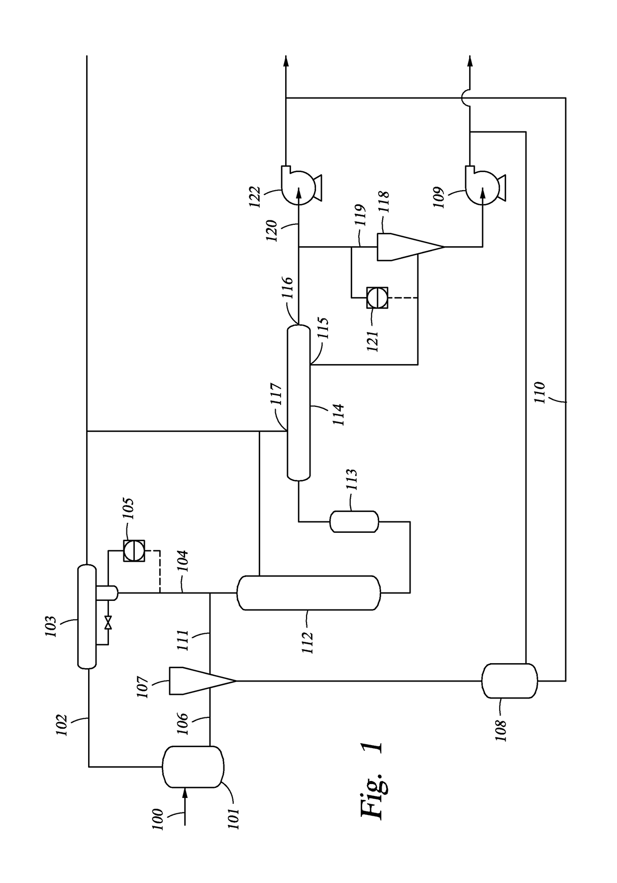
[0021]FIG. 1 is a schematic of a separation system according to one embodiment of the present disclosure. A majority of the components depicted in FIG. 1 are known and common within such ...


PUM

PropertyMeasurementUnit
angleaaaaaaaaaa
angleaaaaaaaaaa
internal diameteraaaaaaaaaa

Abstract

A system and method for enhancing separation of a denser phase liquid from a lighter phase liquid within a multiphase stream. In one example, a cyclonic coalescer has a tubular housing and a plurality of coaxial flow chambers extending in the axial direction of the housing. A swirling element is associated with each of the plurality of coaxial flow chambers. The swirling elements are constructed and arranged to impart a tangential velocity of the stream flowing through the associated flow chamber.

Description

CROSS-REFERENCE TO RELATED APPLICATION[0001]This application is the National Stage of International Application No. PCT / US2013 / 027668, filed 25 Feb. 2013, which claims the priority benefit of U.S. Provisional Patent Application 61 / 617,331, filed 29 Mar. 2012 entitled SYSTEM AND METHOD TO TREAT A MULTIPHASE STREAM, the entirety of which is incorporated by reference herein.FIELD OF INVENTION[0002]This invention generally relates to the field of fluid separation and, more particularly, to the treatment of a multiphase fluid stream in connection with hydrocarbon production activities.BACKGROUND[0003]This section is intended to introduce various aspects of the art, which may be associated with exemplary embodiments of the present invention. This discussion is believed to assist in providing a framework to facilitate a better understanding of particular aspects of the present invention. Accordingly, it should be understood that this section should be read in this light, and not necessaril...

Claims


Application Information

Patent Timeline
Patent Type & Authority Patents(United States)
IPC IPC(8): B01D17/02C10G31/10B01D17/06E21B43/34B01D21/26B01D17/04B04C3/00B04C3/04B03C11/00
CPCB01D17/0217B01D17/045B01D17/06B03C11/00B04C3/04C10G31/10E21B43/34B01D21/267B04C2003/003B04C2003/006
Inventor WHITNEY, SCOTT M.GRAVE, EDWARD J.FOWLER, TRACY A.
Owner EXXONMOBIL UPSTREAM RES CO
Why Eureka
Try Eureka