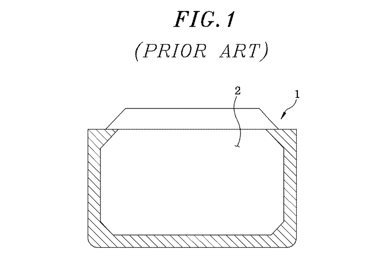
Floating type LNG station
a floating type, station technology, applied in the direction of container discharging methods, passenger handling apparatus, container filling under pressure, etc., can solve the problems of increasing world oil prices, unable to refuel ships during sailing, and increasing lng as fuel, so as to reduce time and space restrictions and manage smoothly
- Summary
- Abstract
- Description
- Claims
- Application Information
AI Technical Summary
Benefits of technology
Problems solved by technology
Method used
Image


Examples
first embodiment
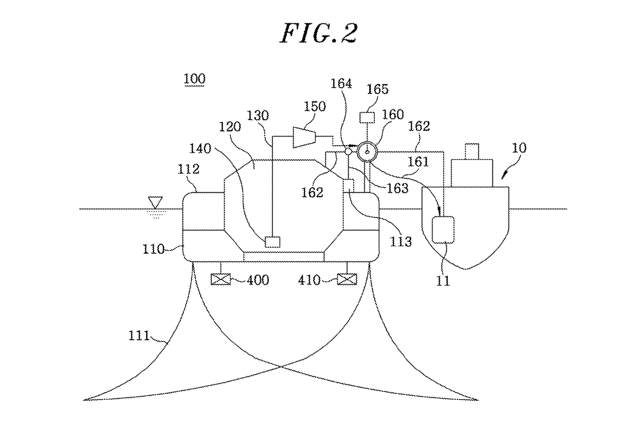
[0034]FIG. 2 is a diagram illustrating a configuration of a floating type LNG station in accordance with the present invention, and FIG. 3 is a diagram illustrating a configuration of a modification example of the floating type LNG station shown in FIG. 2. Particularly, FIG. 2 shows a manner in which the floating type LNG station of the present invention refuels a refueling target with LNG, and FIG. 3 shows a manner in which the floating type LNG station of the present invention is supplied with LNG from an LNG supply ship.
[0035]As shown in FIG. 2, a floating type LNG station 100 in accordance with the first embodiment is used to refuel a refueling target 10, such as a ship or a marine structure, with LNG (Liquefied Natural Gas) utilized as fuel for propulsion, electricity generation, or the like in a state of floating on the sea. The floating type LNG station 100 includes a floating structure 110, an LNG tank 120 provided in the floating structure 110, an LNG line 130 for dischargi...
second embodiment
[0054]FIG. 4 is a diagram illustrating a configuration of a floating type LNG station in accordance with the present invention.
[0055]As shown in FIG. 4, a floating type LNG station, 200 in accordance with the second embodiment includes a floating structure 210, an LNG tank 220 provided in the floating structure 110 so as to store LNG, an LNG line 230 for discharging the LNG from the LNG tank 220, and an LNG pump 240 which is installed at the LNG line 230 so as to provide pumping force for discharge of the LNG, pressurizing pump 251 and 252 which are installed at the LNG line 230 so as to pressurize the LNG, and an unloading unit 260 for supplying a ship or a marine structure with the LNG discharged from the LNG line 230. The above-mentioned components are substantially similar to those of the floating type LNG station 100 in accordance with the first embodiment, and therefore, no description will be given thereof.
[0056]In the present embodiment, particularly, the pressurizing pumps ...
PUM
 Abstract
Description
Claims
Application Information