Centrifugal compressor

a centrifugal compressor and compressor technology, applied in the direction of machines/engines, mechanical equipment, liquid fuel engines, etc., can solve the problems of the surge occurs, and the surging is difficult to suppress the surge limit with the circulating flow of the casing treatment. achieve the effect of improving the surge limi

Active Publication Date: 2017-09-26
TOYOTA JIDOSHA KK
View PDF25 Cites 6 Cited by
  • Summary
  • Abstract
  • Description
  • Claims
  • Application Information

AI Technical Summary

Benefits of technology

[0022]Accordingly, the constricting part increases the speed of gas supplied thereto, and the rectifying part is able to rectify gas supplied to the constricting part in a direction that minimizes the swirl component about the rotational axis and also increases the component in the direction of the rotational axis. As a result, gas immediately after passing through the constricting part is accelerated and made to have a comparatively strong axial component. When such gas is mixed into the circulating flow discharged from the second channel, the component in the direction of the rotational axis in the flow of the mixed gas increases, thereby enabling an improvement in the surge limit.
[0024]Accordingly, with a simple structure, it is possible to rectify gas supplied to the constricting part in a direction that minimizes the swirl component about the rotational axis and also increases the component in the direction of the rotational axis. The rectifying element that “extends parallel to the rotational axis” referred to herein includes a rectifying element that extends in the radiation direction from the rotational axis, but also includes a rectifying element in which a rectifying element extending in such a radiation direction has a virtual line parallel to the rotational axis, and extends in a rotated direction with respect to the virtual line on the rectifying element.
[0026]Accordingly, when viewed from the upstream side in the direction of the rotational axis, the rectifying plate does not project out into the trailing gas channel leading up to the blade leading edge, and intake resistance may be decreased when the impeller sucks up gas.
[0028]Accordingly, a greater effect of improving the surge limit is obtained compared to the case in which the rectifying plate does not extend along the radial direction.
[0030]Accordingly, and similarly to the above, by increasing the component in the direction of the rotational axis in the mixed gas, an improvement in the surge limit becomes possible.
[0033]According to the present invention, there is exhibited an advantageous effect of providing a centrifugal compressor having a circulating casing treatment enabling an improved surge limit.

Problems solved by technology

In such centrifugal compressors, there is a problem in that as the gas flow volume drops, flow reversal or laminar separation is produced in the flow of gas passing through the impeller, and a surge occurs.
In this case, with the device disclosed in Japanese Patent Laid-Open No. 2001-289197, it may become difficult to suppress surging with a circulating flow from the casing treatment.
For this reason, it is difficult to suppress surging with a circulating flow from the exhaust port of the casing treatment.

Method used


Image

  • Centrifugal compressor
  • Centrifugal compressor
  • Centrifugal compressor

Examples


first embodiment

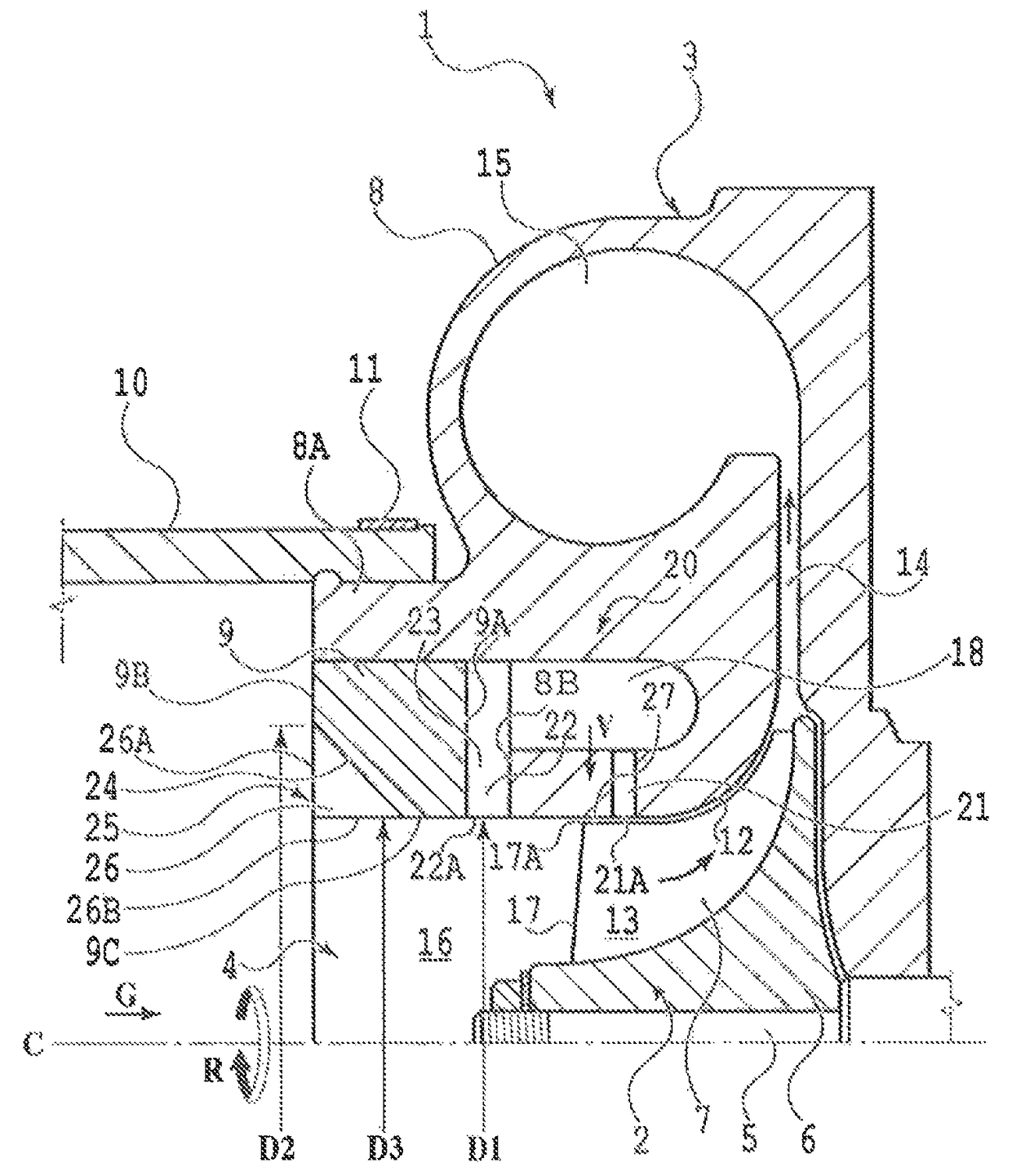
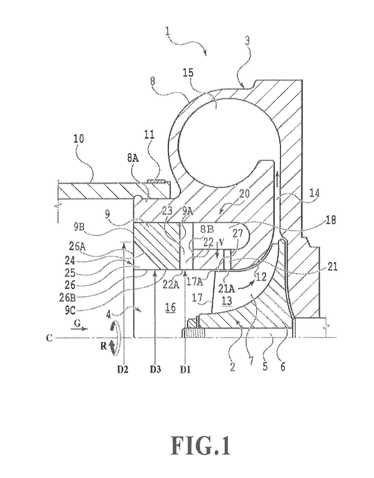
[0052]FIG. 1 illustrates a centrifugal compressor 1 according to a first embodiment of the present invention. The centrifugal compressor 1 is applied as the compressor of a turbocharger installed in an internal combustion engine for a vehicle (particularly for an automobile), and is equipped with an exhaust gas turbine coaxially coupled to the centrifugal compressor 1 on the right, outside the range of the drawing. However, the usage of the centrifugal compressor 1 is arbitrary.

[0053]As illustrated in the drawing, the centrifugal compressor 1 is provided with an impeller 2, a casing 3 that rotatably houses the impeller 2 allowing rotation about a rotational axis C, and a gas channel 4, at least provided in the casing 3, for circulating gas G (in the present embodiment, intake air of the internal combustion engine) passing through the impeller 2 as indicated by the arrow. The impeller 2 is affixed to a shaft 5 that acts as a turbine shaft, and is rotatably driven via the shaft 5 by a...

second embodiment

[0086]In the second embodiment illustrated in FIG. 12, the configuration of the casing treatment 20 differs from the first embodiment. In other words, the first channel 21, the second channel 22, and the front edge face of the treatment hollow part 18 (the rear face 9A of the ring member 9) are tilted so that the outer radial side is positioned farther to the front than the inner radial side. As a result, an improvement in the circulation efficiency of the circulating flow F is possible.

[0087]In addition, the guide vanes 23 are shorter than in the first embodiment, and positioned only inside the second channel 22.

[0088]In addition, a corner part formed by the leading edge 326A and the inner circumferential edge 326B of each rectifying plate 326 is cut out diagonally, and a tapered part 326C is formed in each rectifying plate 326. According to the present embodiment, operational advantages similar to the first embodiment may be exhibited.

third embodiment

[0089]In the third embodiment illustrated in FIG. 13, the installation position of the rectifying plates 426 differs from the first embodiment. In other words, an inlet pipe 30 is connected to the inlet 8A of the casing 3 (specifically, the casing body 8), a constricting part 31 is provided in the inlet pipe 30 (particularly at the trailing edge), and the rectifying plates 426 are provided in the constricting part 31. At this point, the inlet pipe 30 is abutted with the casing 3, and connected to the casing 3 by fastening both with an elastic connecting ring 32 and a clamp band 11. However, other connection methods are also possible.

[0090]The constricting part 31 is formed to gradually constrict the bore of the inlet pipe 30 in a taper shape from a diameter D4 at the upstream edge of the constricting part to the diameter D1 at the downstream edge of the constricting part. Note that the diameter of the gas channel 4 is a constant D1 from the downstream edge of the constricting part t...


PUM


Abstract

A centrifugal compressor having a casing that houses an impeller allowing rotation about a rotational axis C, a gas channel, a treatment hollow part provided inside the casing, a first channel open to the gas channel on the downstream side of the blade leading edge of the impeller, a second channel open to the gas channel at the upstream side of the blade leading edge, a guide vane that imparts a swirl component in an opposite rotational direction of the impeller to gas discharged from the second channel, a constricting part that constricts the gas channel, and a rectifying part that rectifies gas in a direction that minimizes the swirl component about the rotational axis C and also increases the component in the direction of the rotational axis C.

Description

CROSS-REFERENCES TO RELATED APPLICATIONS[0001]This application claims the benefit of Japanese Patent Applications No. 2014-146093, filed Jul. 16, 2014, and No. 2015-078575, filed Apr. 7, 2015, which are hereby incorporated by reference wherein in their entirety.BACKGROUND OF THE INVENTION[0002]Field of the Invention[0003]The present invention relates to a centrifugal compressor, and more particularly, to a centrifugal compressor applied to a turbocharger for a vehicle.[0004]Description of the Related Art[0005]Turbochargers are typically used as superchargers for vehicles. A turbocharger drives a turbine using the energy of the exhaust gas exhausted from the engine, drives a centrifugal compressor coaxially coupled to the turbine, compresses gas (intake air), and supercharges the engine.[0006]In such centrifugal compressors, there is a problem in that as the gas flow volume drops, flow reversal or laminar separation is produced in the flow of gas passing through the impeller, and a s...

Claims


Application Information

Patent Timeline
Patent Type & Authority Patents(United States)
IPC IPC(8): F02B33/40F04D27/02F04D25/02F04D17/10F04D29/28F04D29/44F04D29/42F04D29/68
CPCF02B33/40F04D17/10F04D25/02F04D27/0207F04D29/284F04D29/4206F04D29/4213F04D29/444F04D29/685F05D2220/40F05D2250/51
Inventor NAKAO, HIDEFUMI
Owner TOYOTA JIDOSHA KK
Why Eureka
Try Eureka