
Electrochemical compressor with reactant conduit

a technology of reactant conduit and electric compressor, which is applied in the direction of refrigeration machines, refrigeration components, light and heating apparatuses, etc., can solve the problems of reducing efficiency and adding complexity, and achieve the effect of less nois

Active Publication Date: 2018-03-06
XERGY LTD
View PDF3 Cites 1 Cited by
  • Summary
  • Abstract
  • Description
  • Claims
  • Application Information

AI Technical Summary

Benefits of technology

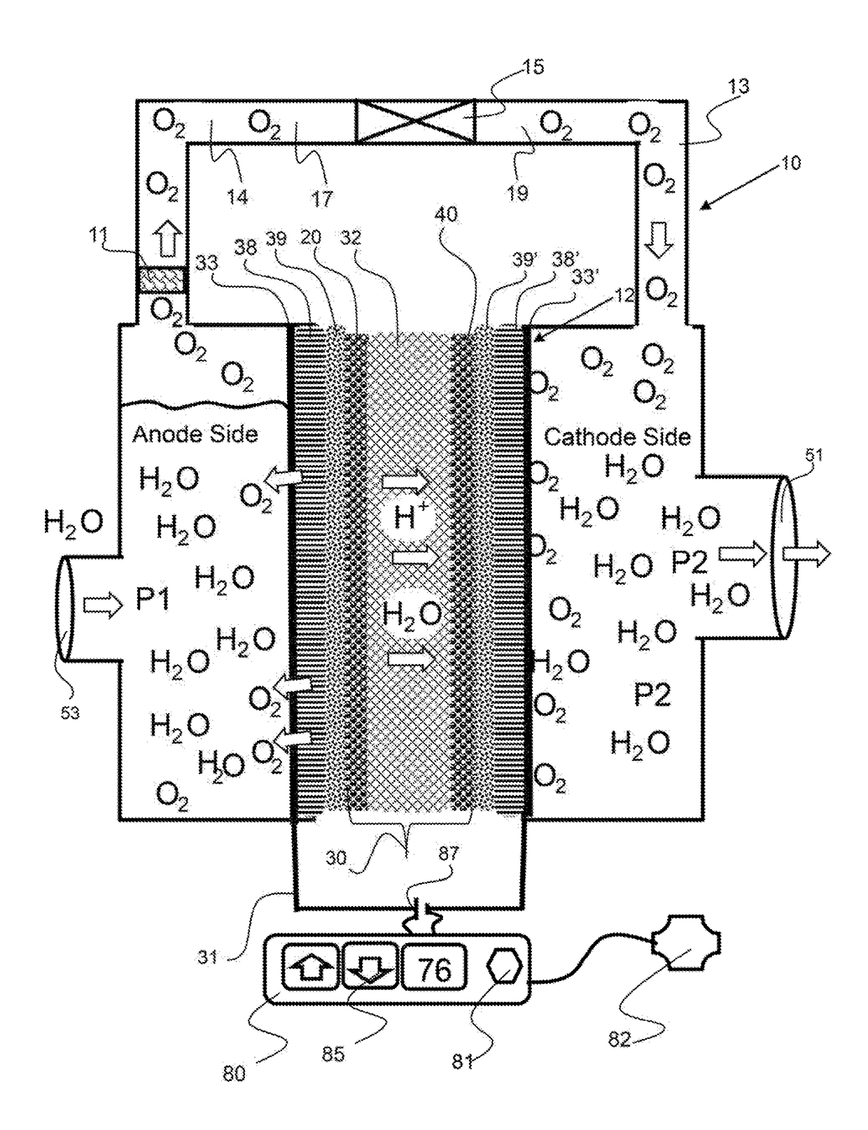
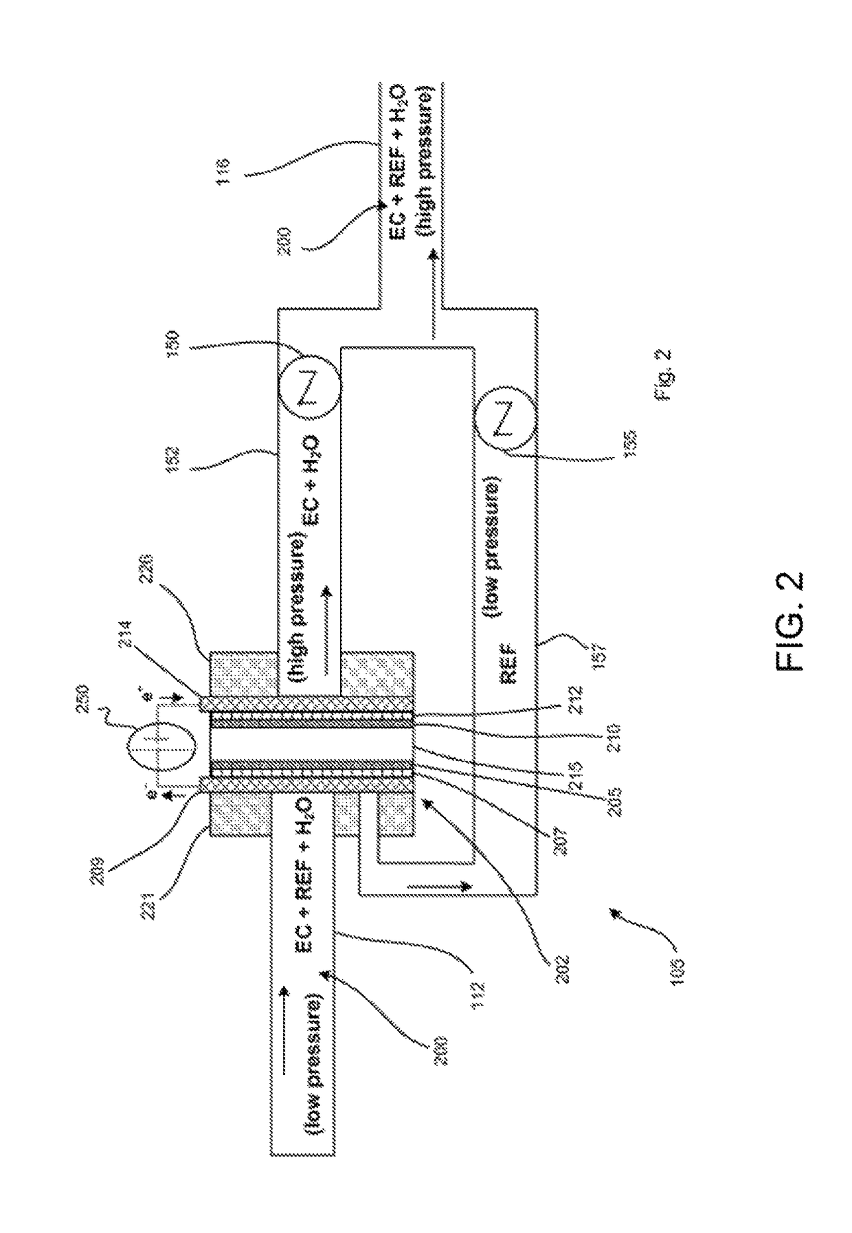
[0008]A transfer device to move the reactant from the low pressure side to the higher pressure side of the electrochemical call may be a one-way flow valve, a venturi nozzle, turbine, fan, pump or any other device that enables the transfer of the second component from the anode side of the electrochemical compressor to the cathode side of the compressor. The nozzle has a head, or tip, that is of the appropriate diameter where the velocity and pressure of the gas exiting is higher than the static pressure of the gas on the cathode side. This allows a gas from the low pressure side, cathode side, to be passed through to the higher pressure side, anode side. This is accomplished through the venturi nozzle that increases the velocity of the gas passing therethrough.
[0009]Any ionic compound that can be decomposed into an ionic component and reactant component may be utilized in the electrochemical compressor system as described herein including, but not limited to, water, methanol, and ammonium for example. In an exemplary embodiment, the working fluid comprises water that is disassociated on the on the anode side into oxygen and protons. The protons pass through the ion conducting membrane, such as an ionomer, to the cathode. The protons drag water through the ion conducting membrane to the cathode side and thereby creates a higher pressure on the cathode side. The oxygen created by the electrolysis of water on the anode side is pumped through the venturi nozzle to the cathode side, where it reacts with the protons to reform water. In this embodiment, hydrogen is not required to be pumped around the system, or through the refrigeration cycle where it reduces efficiency and adds complexity as it does not change phases under these conditions.
[0024]There are several benefits to using carbon dioxide as a refrigerant in a refrigeration system. If carbon dioxide manages to leak out of the system, and make its way up to the ozone layer, the ultraviolet radiation does not break up the molecule to release highly active chlorine radicals that help to deplete the ozone layer. Therefore, carbon dioxide does not deplete the ozone layer.
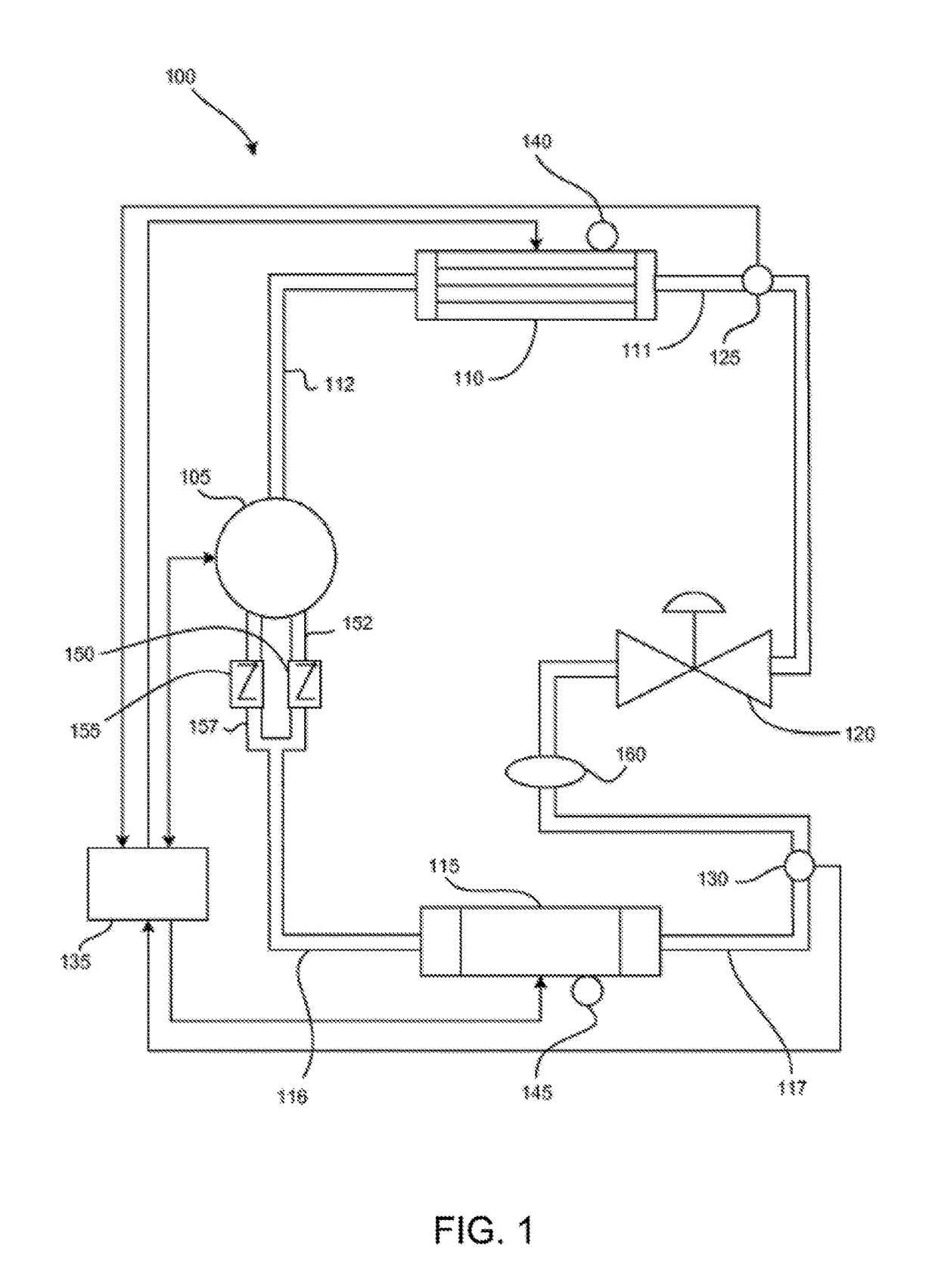
[0026]The vapor compression refrigeration system uses an electrochemical compressor and therefore is modular (that is, it can be of different sizes without limitation). The vapor compression refrigeration system is electrically driven and thus fully electronically controlled. The vapor compression refrigeration system can be considered essentially noiseless, and thus is less noisy than conventional mechanical refrigeration systems. The vapor compression refrigeration system is more efficient than conventional mechanical refrigeration systems

Problems solved by technology

In this embodiment, hydrogen is not required to be pumped around the system, or through the refrigeration cycle where it reduces efficiency and adds complexity as it does not change phases under these conditions.

Method used


Image

  • Electrochemical compressor with reactant conduit
  • Electrochemical compressor with reactant conduit
  • Electrochemical compressor with reactant conduit

Examples


Embodiment Construction

[0037]As used herein, the terms “comprises,”“comprising,”“includes,”“including,”“has,”“having” or any other variation thereof, are intended to cover a non-exclusive inclusion. For example, a process, method, article, or apparatus that comprises a list of elements is not necessarily limited to only those elements but may include other elements not expressly listed or inherent to such process, method, article, or apparatus. Also, use of “a” or “an” are employed to describe elements and components described herein. This is done merely for convenience and to give a general sense of the scope of the invention. This description should be read to include one or at least one and the singular also includes the plural unless it is obvious that it is meant otherwise.

[0038]Certain exemplary embodiments of the present invention are described herein and are illustrated in the accompanying figures. The embodiments described are only for purposes of illustrating the present invention and should not...


PUM

PropertyMeasurementUnit
pressureaaaaaaaaaa
pressureaaaaaaaaaa
pressureaaaaaaaaaa

Abstract

An electrochemical compressor incorporates an electrochemical cell having an anode and a cathode that reacts a working on the anode side into an ionic component and a reactant. The ionic component is transported through an ion conducting media to the cathode. At least a portion of the reactant passes through a reactant conduit that extends from the anode to the cathode. A transfer device, such as a pump or venturi valve configured along the reactant conduit allows the reactant to flow from the anode to the cathode. The reactant and the ionic component are reacted on the cathode to reform the working fluid. A reactant separator may be configured to selectively allow reactant into the reactant conduit. A reactant separator may be a perm-selective layer or a fluid that has high reactant solubility. The working fluid may be water with the ionic component protons and the reactant oxygen.

Description

CROSS REFERENCE TO RELATED APPLICATIONS[0001]This application is a continuation of U.S. application Ser. No. 15 / 289,220 filed on Oct. 10, 2016, entitled Electrochemical Heat Transfer System and currently pending, which is a continuation of U.S. application Ser. No. 13 / 029,006 filed on Feb. 16, 2011, entitled “Electrochemical Heat Transfer System” and issued as U.S. Pat. No. 9,464,822 on Oct. 11, 2016, which is a continuation-in-part of U.S. application Ser. No. 12 / 771,620 filed on Apr. 30, 2010, entitled “Self-Contained Electrochemical Heat Transfer System” and issued as U.S. Pat. No. 8,627,671 on Jan. 14, 2014, which claims the benefit of U.S. provisional patent application No. 61 / 215,131 filed on May 1, 2009, and U.S. application Ser. No. 13 / 029,006 claims priority to U.S. provisional application No. 61 / 305,410 filed on Feb. 17, 2010 and entitled “Electrochemical Heat Pump System for Cooling Electronic Components,” and to U.S. provisional application No. 61 / 347,428, filed May 23, ...

Claims


Application Information

Patent Timeline
Patent Type & Authority Patents(United States)
IPC IPC(8): F25B27/00C09K5/16C25B1/04F25B1/00C25B9/06C09K5/04F25B1/10C25B9/17
CPCC25B9/06C09K5/041C09K5/16C25B1/04F25B1/00Y02E60/366F25B1/10F25B2400/07F25B2400/075Y02E60/36C25B9/17
Inventor BAHAR, BAMDAD
Owner XERGY LTD
Learn More