
Winding with a cooling channel for an electrical machine

a technology of cooling channel and electrical machine, which is applied in the direction of windings, electrical apparatus, dynamo-electric machines, etc., can solve the problems of limited heat dissipation, and achieve the effects of reducing cross section, reducing high temperature of conductor bars, and increasing copper cross sections

Inactive Publication Date: 2017-07-18
SIEMENS AG
View PDF15 Cites 0 Cited by
  • Summary
  • Abstract
  • Description
  • Claims
  • Application Information

AI Technical Summary

Benefits of technology

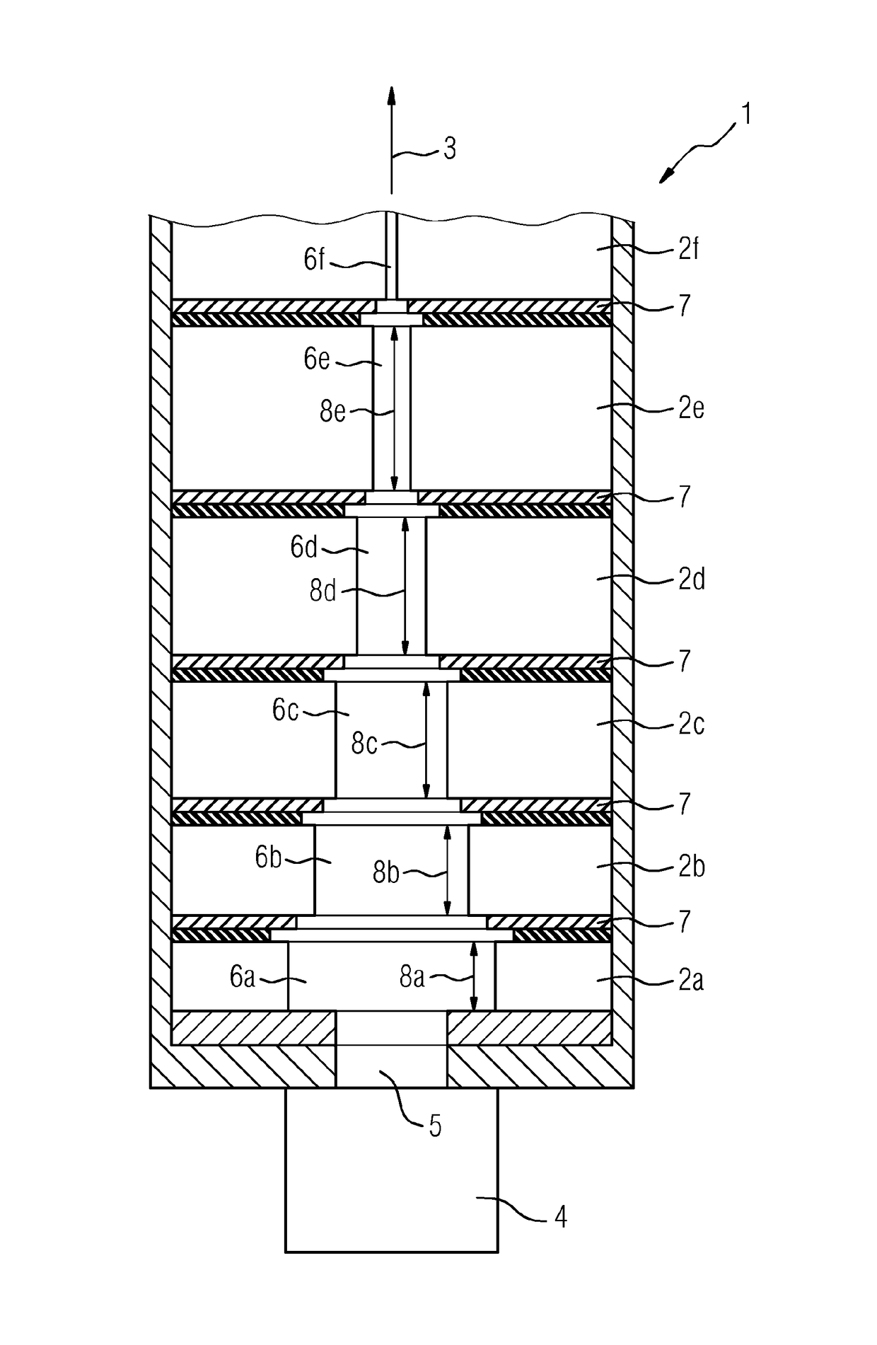
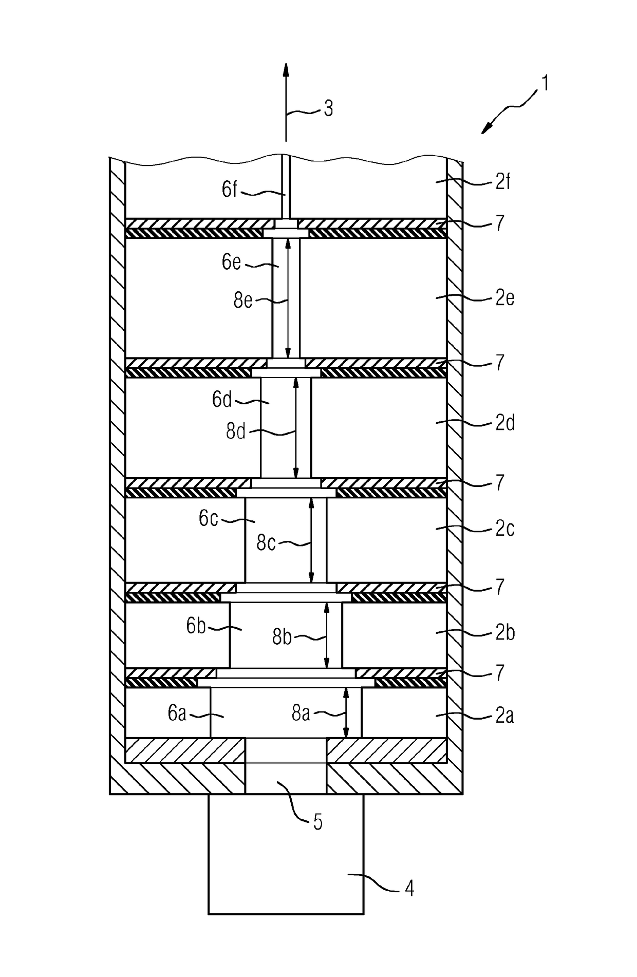
[0013]The temperatures are slightly increased as a result of restricting the cross sections of the lower conductor bars. In the case of the upper conductors, a similar process occurs but in reverse. The comparatively high temperatures of the conductor bars are decreased as a result of the higher copper cross section. Reducing the cross section of the cooling slit in the groove height has likewise an effect, since as a result of the relatively large cooling slit cross section the flow rate of the cooling gas into the lower conductors decreases which leads to an increase of the temperature of the conductor bars. Conversely, the temperatures of the above arranged conductor bars decreases as a result of increasing the cooling gas speeds as a consequence of reducing the cooling slit cross sections. This effect is accordingly supported by means of the swirling effect in the cooling slits with the reducing cross section.
[0014]As a consequence, in accordance with aspects of the invention, the temperatures of the conductor bars are homogenized in the radial direction. A further effect is that the total current that is permitted to flow through the conductor bar can be increased. This leads inter alia to the total cost for the production and the operation of an electrical machine comprising a winding of this type in accordance with the invention being altogether reduced.
[0015]The effect of the winding in accordance with the invention is that the temperatures of the uppermost conductors are reduced. This likewise leads to an increase of the serviceable life of the winding.

Problems solved by technology

The dissipation of heat is limited as a result of the cooling surface and the cooling gas flow.

Method used


Image

  • Winding with a cooling channel for an electrical machine
  • Winding with a cooling channel for an electrical machine

Examples


Embodiment Construction

[0019]The cross sectional view that is illustrated in the FIGURE illustrates a part of a winding 1 for an electrical machine. The winding comprises multiple conductor bars 2a, 2b, 2c, 2d and 2e that are arranged one on top of the other. These conductor bars 2a to 2e are arranged one on top of the other in a radial direction 3. During operation, a cooling medium such as for example air or a gas flows through a groove base duct 4 and at that location through cooling openings 5 through the first conductor bar 2a. The first conductor bar 2a comprises a first cooling slit 6a having a width. An insulation 7 is arranged between the first conductor bar 2a and the second conductor bar 2b. Likewise, an insulation is arranged between the second conductor bar 2b and the third conductor bar 2c and also between the remaining conductor bars 2d etc. that are arranged one on top of the other. The width of the cooling slits 6a, 6b, 6c, 6d, 6e and 6f reduces in the radial direction 3. This means that ...


PUM


Abstract

A winding for an electric machine is provided. The electric machine includes conductor bars which are arranged one above the other and each of which has a cooling slot. The conductor bars are designed such that the height of the conductor bars increases in the radial direction and the effective cooling cross-section decreases in the radial direction.

Description

CROSS REFERENCE TO RELATED APPLICATIONS[0001]This application is the US National Stage of International Application No. PCT / EP2013 / 062986 filed Jun. 21, 2013, and claims the benefit thereof. The International Application claims the benefit of European Application No. EP12178424 filed Jul. 30, 2012. All of the applications are incorporated by reference herein in their entirety.FIELD OF INVENTION[0002]The invention relates to a winding for an electrical machine, said winding having multiple conductor bars that are arranged one on top of the other, wherein the conductor bars comprise in each case a cooling slit that is embodied in a downwards direction.BACKGROUND OF INVENTION[0003]An electrical machine such as by way of example a turbo generator is disclosed in EP 1 742 330 A1. An electrical machine of this type comprises a rotor that can be driven and is mounted in such manner that it can rotate and said rotor is also known as an armature, said electrical machine also comprises a stat...

Claims


Application Information

Patent Timeline
Patent Type & Authority Patents(United States)
IPC IPC(8): H02K9/00H02K3/00H02K3/24H02K3/12
CPCH02K3/24H02K3/12
Inventor KOWALSKI, WALDEMARLEHMANN, CHRISTOPH
Owner SIEMENS AG
Learn More