Liner, flow sleeve and gas turbine combustor each having cooling sleeve

a technology of flow sleeve and gas turbine combustor, which is applied in the direction of engine components, continuous combustion chambers, lighting and heating apparatus, etc., can solve problems such as strength loss, and achieve the effect of increasing cooling performance and reducing or avoiding pressure loss

Active Publication Date: 2018-10-09
DOOSAN HEAVY IND & CONSTR CO LTD
View PDF61 Cites 3 Cited by
  • Summary
  • Abstract
  • Description
  • Claims
  • Application Information

AI Technical Summary

Benefits of technology

[0016]Accordingly, the present disclosure has been made in view of the above-mentioned problems, and it is an object of the present disclosure to provide a liner, a flow sleeve and a gas turbine combustor each having a cooling sleeve, thus increasing cooling performance through collision cooling, while reducing or avoiding loss of pressure.
[0017]It is another object of the present disclosure to provide a liner, a flow sleeve and a gas turbine combustor each having a cooling sleeve, thus enhancing collision cooling performance, mixing cooling performance according to flows, cooling performance of the liner, and durability of the gas turbine combustor and reducing the maintenance cost of the gas turbine combustor.
[0028]According to a third aspect of the present disclosure, there is provided a gas turbine combustor including a liner, a transition piece and a cooling sleeve. In the liner fuel injected from a fuel nozzle of a gas turbine mixes with compressed air and is burned. The liner is encompassed by a flow sleeve in which cooling holes are formed and cooled by way of the air supplied through the cooling holes. High temperature gas produced in the liner is transmitted through the transition piece while increasing the speed of the gas transmitted therefrom. The transition piece is encompassed by a perforated sleeve and compressed air supplied through holes formed on the perforated sleeve collide against the transition piece to allow the colliding air to flow to a space portion between the liner and the flow sleeve. The cooling sleeve is mounted between the flow sleeve and the liner to divide the air supplied through the cooling holes of the flow sleeve and the compressed air flowing to the space portion between the liner and the flow sleeve after colliding against the transition piece.

Problems solved by technology

Such low heat transfer rate causes a high temperature on the surface of the liner 110, which results in the loss of strength.

Method used


Image

  • Liner, flow sleeve and gas turbine combustor each having cooling sleeve
  • Liner, flow sleeve and gas turbine combustor each having cooling sleeve
  • Liner, flow sleeve and gas turbine combustor each having cooling sleeve

Examples


first embodiment

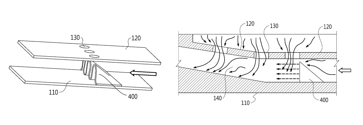
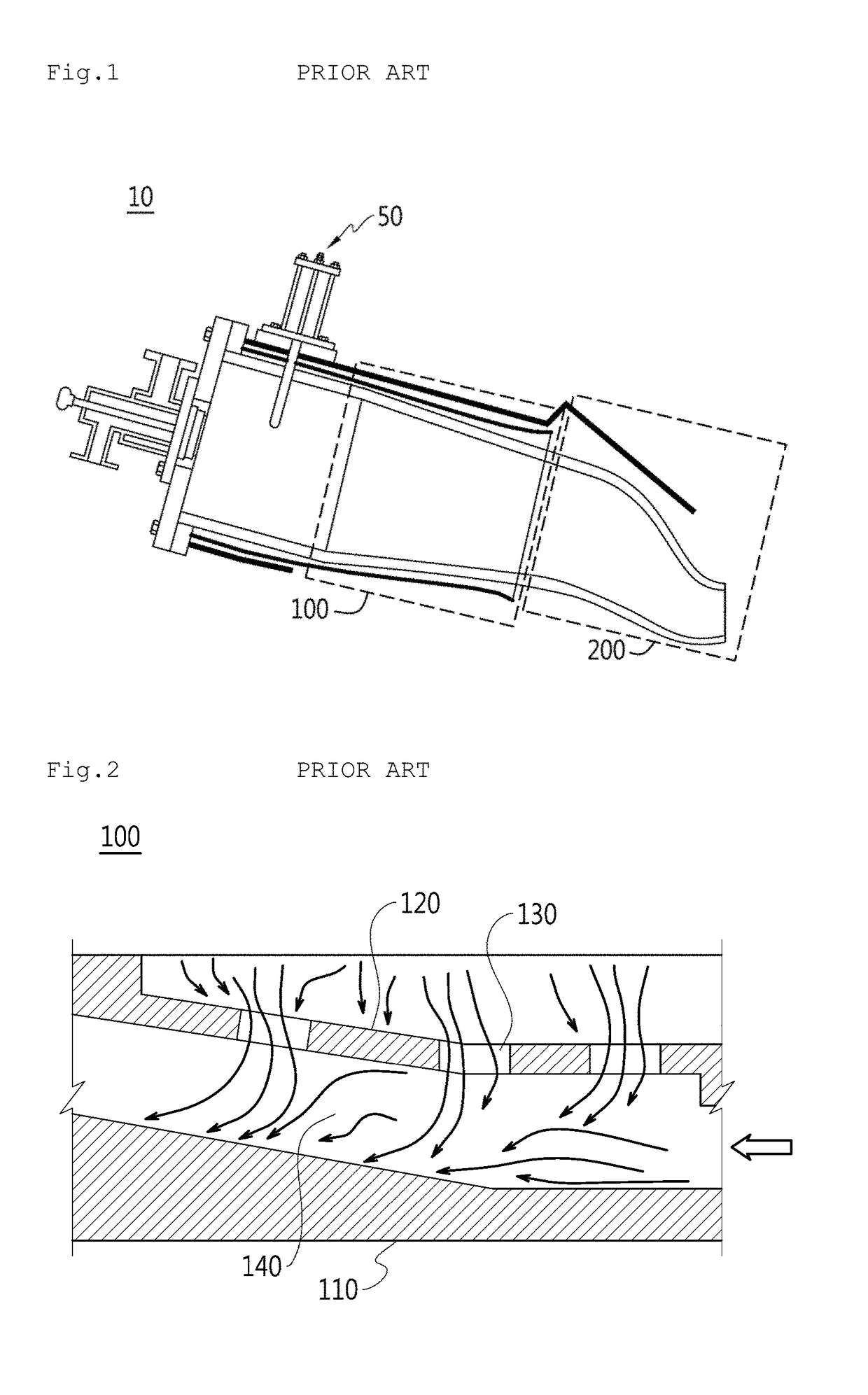
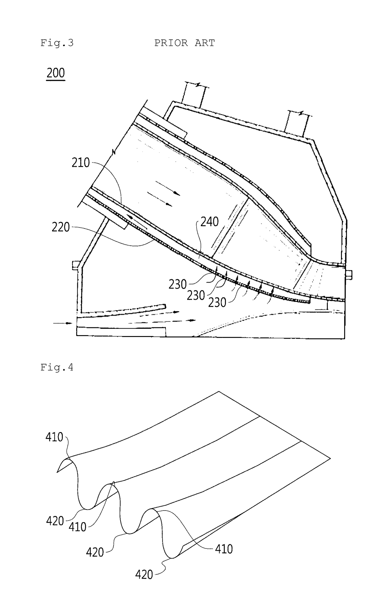
[0046]Referring to FIGS. 5 and 6, there is provided a liner 110 for a gas turbine combustor according to the present disclosure. In the gas turbine combustor, fuel is injected from a fuel nozzle, mixes with compressed air, and is burned. The gas turbine combustor includes a transition piece 210 through which high temperature gas produced in the liner 110 is transmitted while increasing the transmission speed of the gas. The liner 110 is disposed in (in some cases being encompassed by) a flow sleeve 120 in which cooling holes 130 are formed. The liner 110 is cooled by way of the air supplied through the cooling holes 130. The transition piece 210 is disposed in (in some cases being encompassed by) a perforated sleeve 220 and compressed air supplied through holes formed on the perforated sleeve 220 collides against the transition piece 210 to allow the colliding air to flow to a space portion 140 between the liner 110 and the flow sleeve 120. The liner 110 includes a cooling sleeve 40...

second embodiment

[0059]Referring to FIGS. 7 and 8, there is provided a flow sleeve 120 for a gas turbine combustor according to the present disclosure. In the gas turbine combustor, fuel is injected from a fuel nozzle, mixes with compressed air, and is burned. and the gas turbine combustor includes a transition piece 210 through which the high temperature gas produced in the liner 110 is transmitted while increasing the transmission speed of the gas. The liner 110 is disposed in (in some cases being encompassed by) the flow sleeve 120 in which cooling holes 130 are formed. The liner 110 is and cooled by way of the air supplied through the cooling holes 130. Transition piece 210 is disposed in (in some cases being encompassed by) a perforated sleeve 220 and compressed air supplied through holes formed on the perforated sleeve 220 collides against the transition piece 210 to allow the colliding air to flow to a space portion 140 between the liner 110 and the flow sleeve 120. The flow sleeve 120 includ...

third embodiment

[0067]According to the present disclosure, a gas turbine combustor has a liner 110 in which fuel injected from a fuel nozzle of a gas turbine mixes with compressed air and is burned. The gas turbine combustor includes a transition piece 210 through which the high temperature gas produced in the liner 110 is transmitted while increasing the transmission speed of the gas. The liner 110 is disposed in (in some cases being encompassed by) a flow sleeve 120 in which cooling holes 130 are formed. The liner 140 is cooled by way of the air supplied through the cooling holes 130. The transition piece 210 is disposed in (in some cases being encompassed by) a perforated sleeve 220 and compressed air supplied through holes formed on the perforated sleeve 220 collides against the transition piece 210 to allow the colliding air to flow to a space portion 140 between the liner 110 and the flow sleeve 120. The gas turbine combustor includes a cooling sleeve 400 mounted thereon to divide the air sup...


PUM


Abstract

A gas turbine combustor includes a liner and a transmission piece. Fuel injected in the liner from a fuel nozzle of a gas turbine mixes with compressed air. High temperature gas produced in the liner is transmitted through the transmission piece. The liner is disposed in a flow sleeve in which cooling holes are formed. The transition piece is disposed in a perforated sleeve. Compressed air supplied through holes formed in the perforated sleeve collides with the transition piece. The liner includes a cooling sleeve disposed thereon that divides the air supplied through the cooling holes of the flow sleeve and the compressed air flowing to a space portion between the liner and the flow sleeve.

Description

CROSS-REFERENCE TO RELATED APPLICATIONS[0001]This application claims priority to Korean Application No. 10-2014-0005741, filed Jan. 16, 2014, the contents of which are incorporated herein in their entirety.BACKGROUND[0002]The present disclosure relates to a liner for a gas turbine combustor, a flow sleeve for a gas turbine combustor, and a gas turbine combustor, and more particularly, to a liner, a flow sleeve and a gas turbine combustor each having a cooling sleeve.[0003]A turbine is a mechanical device that extracts an impulsive or repulsive force from a flow of a compressed fluid like gas and converts it into a rotary force. If steam is used as the fluid, it is called a steam turbine, and if combustion gas is used as the fluid, it is called a gas turbine.[0004]The thermal cycle of the gas turbine is the Brayton cycle, and the gas turbine is composed of three main components, that is, a compressor, a combustor, and a turbine. According to the operating principle of the gas turbine...

Claims


Application Information

Patent Timeline
Patent Type & Authority Patents(United States)
IPC IPC(8): F23R3/54F02C7/18F23R3/00F23R3/02
CPCF23R3/54F02C7/18F23R3/002F23R3/02F23R2900/03045F23R2900/03043F23R2900/03044F02C7/22F23R3/42
Inventor KIM, YOUNG BONGCHOE, JINHOONROH, UJIN
Owner DOOSAN HEAVY IND & CONSTR CO LTD
Why Eureka
Try Eureka