Platform assembly and a method for manufacturing an elevator car and an elevator car

a technology for elevator cars and platforms, applied in the direction of sheet joining, building lifts, fastening means, etc., can solve the problems of difficult and slow assembly of elevator cars, large parts are heavy to move and require more space, and the known platform structures are not well suited in practice for being assembled

Active Publication Date: 2017-10-03
KONE CORP
View PDF12 Cites 1 Cited by
  • Summary
  • Abstract
  • Description
  • Claims
  • Application Information

AI Technical Summary

Benefits of technology

[0004]It is brought forward a new platform assembly, comprising a first platform module having a planar upper face and an elongated front face, a second platform module having a planar upper face and an elongated front face, a locking member for locking the front faces of the first and second platform modules to each other when they are set against each other, which locking member is movably mounted on the first platform module. The locking member is mounted on the first platform module movably in the longitudinal direction of the front face. At least one of the locking member and the second platform comprises a locking protrusion protruding from the front face of the platform module in question, and the other of the locking member and the second platform comprises a locking slot arranged to receive said locking protrusion when the front faces of the platform modules are set against each other, and in that an edge of the locking protrusion is arranged to move behind an edge of the locking slot when the locking member is moved in said longitudinal direction of the front face, thereby locking the platform modules to each other. Thus, one or more of the aforementioned advantages can be achieved. In particular, the modules of the platform assembly can be rigidly locked to each other. The platform assembly is suitable for forming part of a floor of an elevator car. The mechanism can be used effectively to align elevator car platform modules together tightly, and it's easy to observe the alignment of flooring materials. The platform assembly can be mounted easily on top of the car frame (e.g. on the raw car floor of the car frame). The platform assembly is also fast to install because the fitter can stay on top of floor and doesn't have to go under the car during installation. The locking ensures a high quality top surface for the floor of an elevator car.
[0005]In a preferred embodiment both the locking member mounted on the first platform module and the second platform module comprises a locking protrusion protruding from the front face of the platform module in question, and both the locking member mounted on the first platform module and the second platform comprises a locking slot, and the locking slot of the locking member is arranged to receive the locking protrusion of the second platform and the locking slot of the second platform is arranged to receive the locking protrusion of the locking member when the front faces of the platform modules are set against each other, edges of said locking protrusions being arranged to move behind edges of said locking slots when the locking member is moved in the direction of the front face. In this way, a double-locking effect is achieved. Thereby, the modules are reliably locked to each other. The rigidity of the connection is further facilitated and the seam area of the platform can be made unnoticeable, e.g. for the passenger of the car.
[0006]In a preferred embodiment, the platform assembly comprises a screw means comprising a screw member, via which screw means the locking member is mounted on the first platform module movably such that the locking member is moved in the longitudinal direction of the front face by rotating the screw member of the screw means. These screw means facilitate accurate, forceful, holding and reliable locking movement easily and with simple tools. Preferably, the rotational axis of the screw member is aligned in the longitudinal direction of the front face. Preferably, the screw means is in the form of a nut-and-bolt-pair.
[0022]The elevator as described anywhere above is preferably, but not necessarily, installed inside a building. The elevator is preferably of the type where the car is arranged to serve two or more landings. Then, the car preferably responds to calls from landing and / or destination commands from inside the car so as to serve persons on the landing(s) and / or inside the elevator car. Preferably, the car has an interior space suitable for receiving a passenger or passengers. The car may be provided with a floor, a ceiling, walls and at least one door these all forming together a closable and openable interior space. In this way, it is well suitable for serving passengers.

Problems solved by technology

The problem with this type of installation is that the elevator car is difficult and slow to assemble.
Large parts are heavy to move and require more space.
These problems are met especially when the elevator car is intended to be assembled inside the hoistway.
However, these known platform structures have not been well suitable in practice for being assembled in the hoistway, because an accurate assembly typically requires use of complicated welding equipment and handling of large amount of components.
However, in the known solutions the modules have been complicated to fix to each other rigidly.
In particular, they have not allowed forming of the platform of several smaller platform modules such that the platform modules together form a platform with upper face area which is the sum of the upper face areas of the platform modules.

Method used


Image

  • Platform assembly and a method for manufacturing an elevator car and an elevator car
  • Platform assembly and a method for manufacturing an elevator car and an elevator car
  • Platform assembly and a method for manufacturing an elevator car and an elevator car

Examples


Embodiment Construction

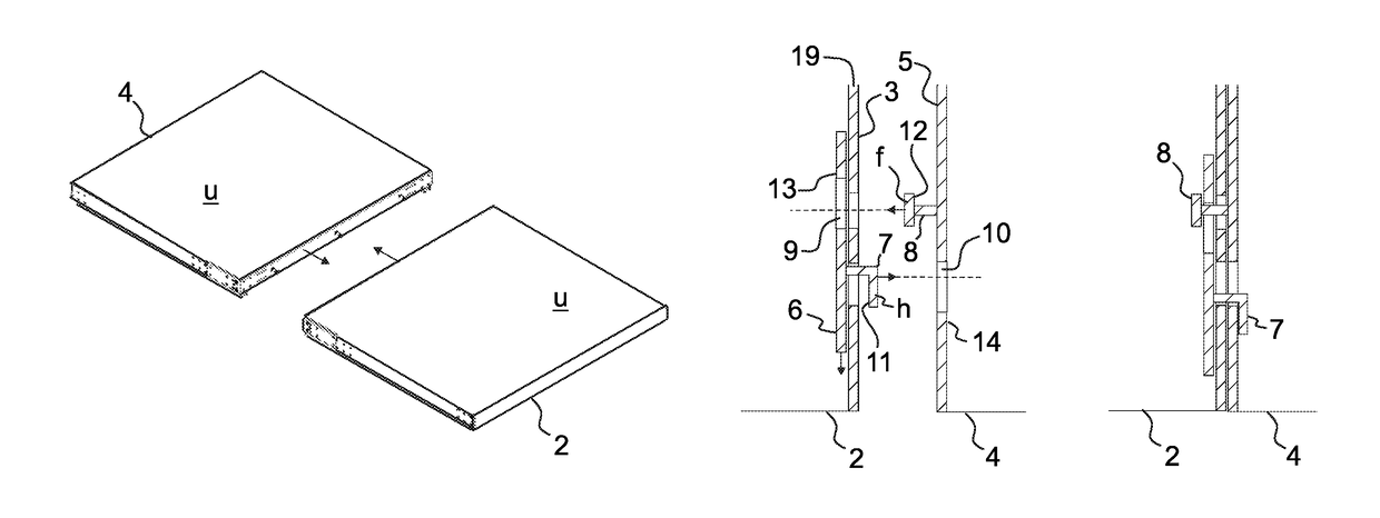
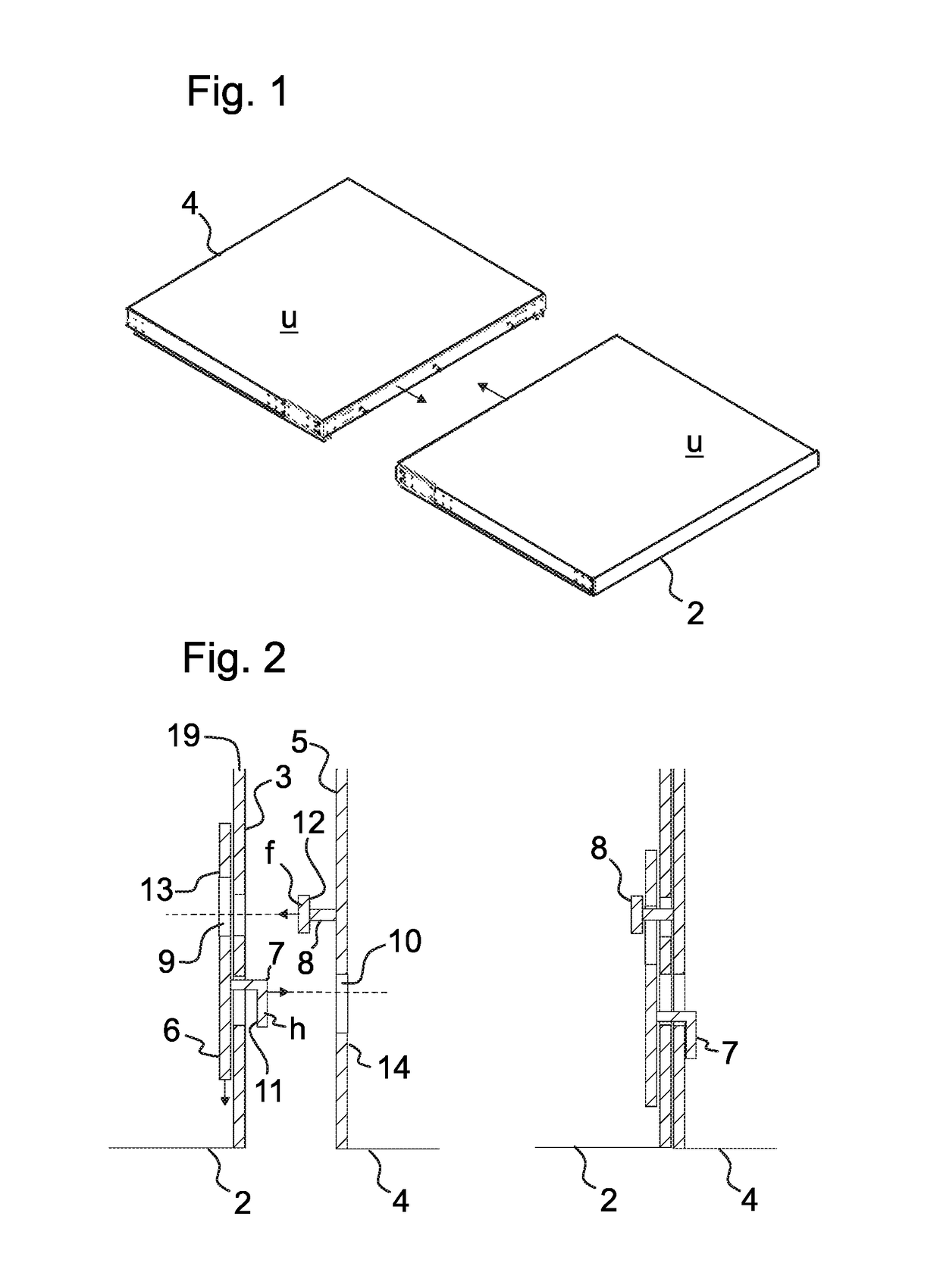
[0035]FIG. 1 illustrates a platform assembly 1 in a non-assembled state, i.e. in a state where its platform modules are not yet locked to each other. The platform assembly 1 comprises a first platform module 2 having a planar upper face u, and an elongated front face 3 forming an elongated flank of the first platform module 2. The platform assembly 1 further comprises a second platform module 4 having a planar upper face u, and an elongated front face 5 forming an elongated flank of the second platform module 4.

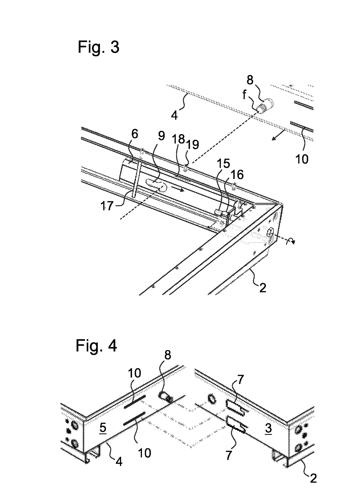
[0036]The platform assembly 1 further comprises a locking member 6, illustrated in FIG. 2, for locking the front faces 3, 5 of the first and second platform modules 2, 4 to each other when they are set against each other. The locking member 6 is movably mounted on the first platform module 2 to be moved with a movement for locking from a released position to a locking position and vice versa. More specifically, the locking member 6 is mounted on the first platform module 2 mo...


PUM

PropertyMeasurementUnit
structureaaaaaaaaaa
bearing structureaaaaaaaaaa
widthaaaaaaaaaa

Abstract

A platform assembly includes a first platform module having an elongated front face, a second platform module having an elongated front face, and a locking member for locking the front faces of the first and second platform modules to each other. The locking member is movably mounted on the first platform module in a longitudinal direction of the front face thereof, and at least one of the locking member and the second platform includes a locking protrusion, and the other of the locking member and the second platform includes a locking slot, wherein the locking protrusion is received by the locking slot and protrudes from the front face of the first platform module. An edge of the locking protrusion is behind an edge of the locking slot when the locking member is moved in said longitudinal direction of the front face, thereby locking the platform modules to each other.

Description

FIELD OF THE INVENTION[0001]The invention relates to structure and installation of a platform, in particular to structure and installation of a platform of a car of an elevator which is meant for transporting passengers and / or goods on top of the platform.BACKGROUND OF THE INVENTION[0002]Elevator cars typically have a platform on top of which passengers and / or goods can be transported. The platform typically forms the load bearing structure of the cabin floor. It may be covered with a decorative panel but this is not always necessary as the platform itself may comprise a decorative surface plate. The cabin is a box-like structure with walls, ceiling, a floor and possibly door(s), which together define the interior space for receiving the load to be transported. The cabin may be a self-carrying structure and form as such the complete elevator car, or alternatively the cabin can be mounted on a car frame via the platform. In prior art, there are numerous different platform solutions. ...

Claims


Application Information

Patent Timeline
Patent Type & Authority Patents(United States)
IPC IPC(8): B66B11/02B21D39/03F16B5/00
CPCB66B11/0226B66B11/0206F16B5/0088F16B5/0036Y10T29/49826
Inventor MANNER, TIMONATARAJAN, NITHIL KARIMPANACKALLAPPALAINEN, JOUNIKOLI, PETRISAARELA, SAMIHAIKONEN, AKITIAINEN, VESAHALONEN, PEKKAVENHO, ANSSIKOLEHMAINEN, SEPPO
Owner KONE CORP
Why Eureka
Try Eureka