Method for manufacturing magnet-conductive device and glue-injectable punch structure thereof

a technology of magnet conductive and punch structure, which is applied in the manufacture of stator/rotor body, electrical apparatus, dynamo-electric machines, etc., can solve the problems of high cost, high cost, and high cost of conventional motor stators, so as to reduce iron loss, effectively inhibit, and increase coupling strength

Active Publication Date: 2017-10-03
METAL INDS RES & DEV CENT
View PDF3 Cites 0 Cited by
  • Summary
  • Abstract
  • Description
  • Claims
  • Application Information

AI Technical Summary

Benefits of technology

[0003]The primary object of the present invention is to provide a method for manufacturing a magnet-conductive device, wherein the method includes punching a plate by using a glue-injectable punch structure in a punch process and injecting a gel onto an upper surface of the plate via the glue-injectable punch structure at the moment the punch action is performed. Thus, when the next punching process is performed, another plate enables to engage with mentioned plate via compression force of the glue-injectable punch structure to increase the coupling strength between adjacent plates. In addition, the gel is an insulating medium for lowering iron loss and burr eddy-current loss, and the short issue is effectively inhibited. When the magnet-conductive device of the present invention is applicable to a motor, a wind shear phenomenon is not occurred to avoid vibrations and sounds of wind shear as long as the motor is under operation owing to the gap between adjacent plates filled with the gel.
[0006]The present invention simplifies the process for stacking plural plates and adhere adjacent plates from each other by compression force of punching and injected glue to increase the coupling strength between adjacent plates. The gel of the present invention belongs to an insulating medium, which may lower the iron loss and burr eddy-current loss of stacked magnet-conductive plates, and the short issue is effectively inhibited.

Problems solved by technology

However, the process for manufacturing conventional motor stator is relatively complicated.
When the stator of a motor is in operation, a wind shear phenomenon is occurred to result in vibrations and sounds of wind shear.
Additionally, conventional motor stator likely generates iron loss, burr eddy-current loss and short issues.

Method used


Image

  • Method for manufacturing magnet-conductive device and glue-injectable punch structure thereof
  • Method for manufacturing magnet-conductive device and glue-injectable punch structure thereof
  • Method for manufacturing magnet-conductive device and glue-injectable punch structure thereof

Examples


Embodiment Construction

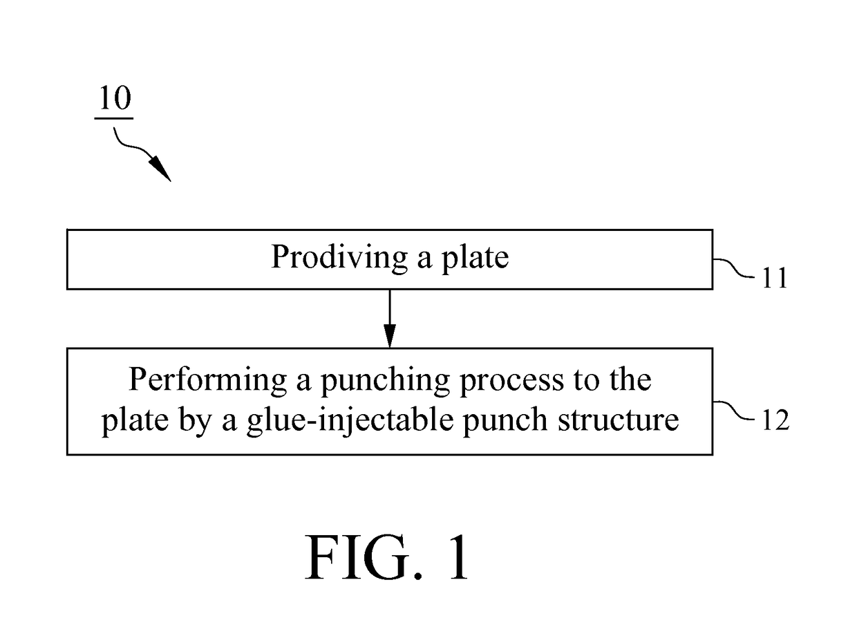
[0015]With reference to FIG. 1, a method 10 for manufacturing a magnet-conductive device includes the step 11 of providing a plate and another step 12 of performing a punching process to the plate by using a glue-injectable punch structure.

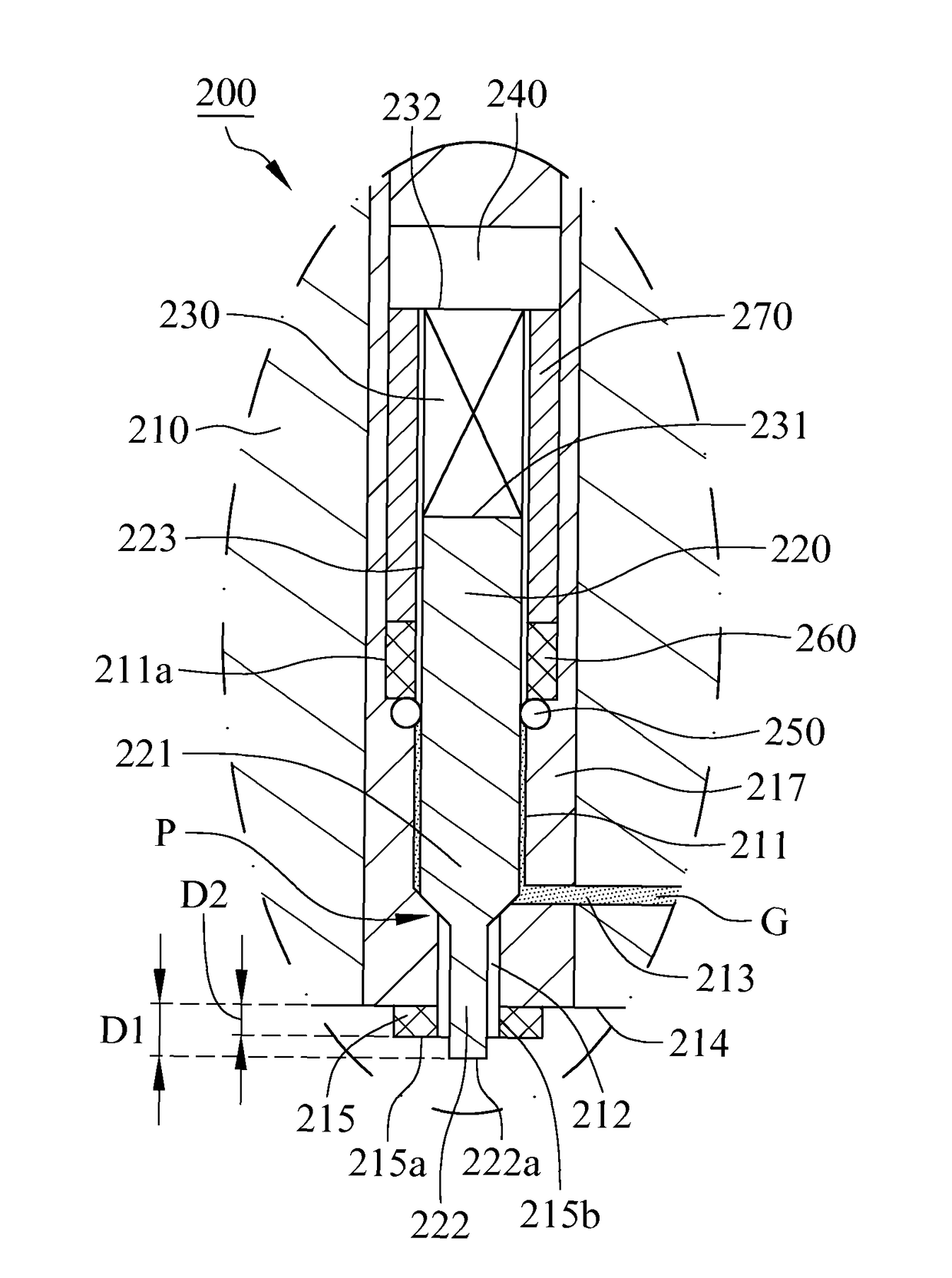
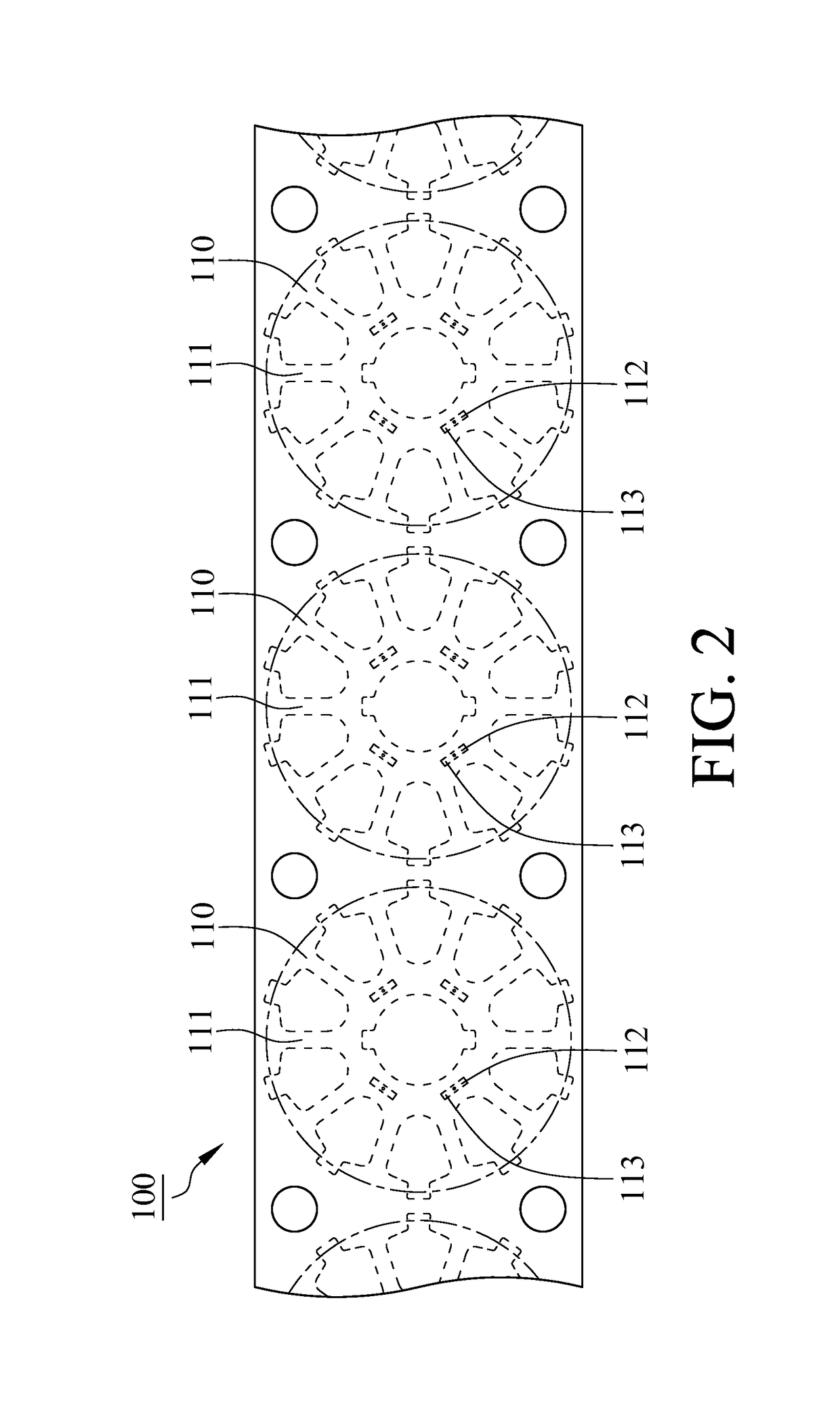
[0016]Referring to FIGS. 1 and 2, in the step 11 of providing a plate, the plate 100 comprises a plurality of compression portions 110, each of the compression portions 110 comprises a surface 111 having a riveting area 112 and a filling area 113, in this embodiment, the filling area 113 is located on the riveting area 112. With reference to FIGS. 1 and 3, in the step 12 of performing a punching process to the plate by using a glue-injectable punch structure, the glue-injectable punch structure 200 is engaged with a punching module 300 to perform the punching process, wherein the punching module 300 comprises an upper mold 310, a lower mold 320, a pressing plate 330 and a supplying apparatus 340. The glue-injectable punch structure 200 is mounted ...


PUM

PropertyMeasurementUnit
circular shapeaaaaaaaaaa
eddy-current lossaaaaaaaaaa
compression forceaaaaaaaaaa

Abstract

A method for manufacturing a magnet-conductive device includes performing a punch process to a plate by a glue-injectable punch structure, wherein the glue-injectable punch structure includes a punch head and a control member. The punch head comprises an accommodating cavity, an injection hole and an inlet, and a supply channel is formed by the accommodating cavity, the injection hole and the inlet. The control member selectively obstructs the supply channel or permits the supply channel into conduction. By using the method for manufacturing the magnet-conductive device, the stack between plural plates is simplified, and the coupling strength between adjacent plates is enhanced. In addition, this invention considers the gel between adjacent plates to be insulating medium to lower the iron loss of the magnet-conductive plates.

Description

FIELD OF THE INVENTION[0001]The present invention generally relates to a method for manufacturing a magnet-conductive device, particularly relates the method in performing a punch process to a plate by using a glue-injectable punch structure and injecting a gel to the plate at the moment the action of the punch is performing.BACKGROUND OF THE INVENTION[0002]A conventional method for manufacturing a conventional motor stator is described as below. Punching plural silicon steel plates to form plural I-shaped plates; stacking all the I-shaped plates to form plural sets of I-shaped bars and adhering each set of the I-shaped bars with a gel; winding plural coils at each set of the I-shaped bars; arranging the I-shaped bars into a circular shape; eventually coating peripheral of each set of the I-shaped bars with a glue to fix the I-shaped bars therefore forming a stator. However, the process for manufacturing conventional motor stator is relatively complicated. Besides, the gel merely co...

Claims


Application Information

Patent Timeline
Patent Type & Authority Patents(United States)
IPC IPC(8): B29C65/72H02K15/02
CPCH02K15/02H02K2201/09
Inventor TU, KUO-YINTSAI, HSING-CHIHWANG, HSIN-TESUN, YI-WEI
Owner METAL INDS RES & DEV CENT
Why Eureka
Try Eureka