X-ray mammography and/or breast tomosynthesis using a compression paddle

a compression paddle and x-ray technology, applied in mammography, medical science, diagnostics, etc., can solve the problems of image artifacts, inability to position and manipulate the breast during the technician's work, and non-uniform distribution of compression force throughout the breast, so as to improve breast imaging and patient comfort.

Active Publication Date: 2017-10-10
HOLOGIC INC
View PDF53 Cites 11 Cited by
  • Summary
  • Abstract
  • Description
  • Claims
  • Application Information

AI Technical Summary

Benefits of technology

[0002]A significant patient concern in x-ray mammography and breast tomosynthesis is the discomfort the patient may feel when the breast is compressed, typically, between two rigid plastic surfaces, with sufficient force to immobilize the breast and spread out the breast tissues for x-ray imaging. One challenge is to ensure that the imaged field includes the desired amount of breast tissue. The reasons for using compression include: (1) to make the breast thinner in the direction of x-ray flux and thereby reduce patient radiation exposure from the level required to image the thicker parts of a breast that is not compressed; (2) to make the breast more uniform in thickness in the direction of x-ray flux and thereby facilitate more uniform exposure at the image plane over the entire breast image; (3) to immobilize the breast during the x-ray exposure and thereby reduce image blurring; and (4) to bring breast tissues out from the chest wall into the imaging exposure field and thus image more tissue. As the breast is being compressed, typically a technician manipulates the breast to position it appropriately and counter the tendency that compression has of pushing breast tissue toward the chest wall and out of the image field.
[0003]Standard compression methods for mammography and tomosynthesis use a movable, rigid clear plastic compression paddle in which the surfaces of the paddle are perpendicular to one another. The breast is placed on a breast platform that typically is flat, and the paddle is then compressed onto the breast, usually while a technician or other health professional is holding the breast in place and perhaps manipulates the breast to ensure proper tissue coverage in the image receptor's field of view and to help spread the breast.
[0005]Some systems improve patient comfort by providing compression paddles that tilt as the breast is being compressed. A tilting paddle arrangement is available in various paddle sizes from Lorad of Danbury, Conn., a division of the assignee hereof, Hologic, Inc. of Bedford, Mass., under the trade name F.A.S.T. (of FAST). This tilting paddle provides more uniform compression across the breast, and more comfortable breast examinations.
[0006]Nonlimiting examples of various approaches to compression paddles and systems therefor include U.S. Pat. Nos. 3,971,950; 5,474,072; 5,506,877 and 6,974,255, U.S. Patent Application Publication Nos. 2005 / 0008117, 2006 / 0050844, and 2013 / 0051520, and Japanese Patent Application Publication Nos. 2011-206438 and 2011-206439. Other methods for improving patient comfort have been proposed and some have been in clinical use to improve patient comfort. One is the use of relatively thin foam pads that are placed above and / or below the breast. The pad deforms to some extent during the compression procedure and may provide improved comfort by spreading out the pressure to a greater extent than using a hard-surfaced paddle and / or breast platform alone. One such pad system is discussed in commonly owned U.S. Pat. Nos. 6,968,033, 6,765,984, 6,577,702, and 7,505,555, and published U.S. Patent Application Publication No. 2003 / 0007597. Another pad system is proposed in U.S. Pat. Nos. 6,850,590 and 6,975,701 and published U.S. Patent Application Publication Nos. 2006 / 0050844, US 2004 / 0156472 and 2003 / 0099325. Such pads are not transparent to visible light. As a result, if such a pad is between the breast and the compression paddle, the breast will not be visible through the paddle, and this can impair the technician's effort to position and manipulate the breast during compression. The pad needs to be made of fairly dense thin form, so as to provide meaningful deformability when compressed under or above the breast. If the foam pad slips during positioning and as a result does not cover the entire imaging field, an edge of the pad may cause image artifacts.

Problems solved by technology

One challenge is to ensure that the imaged field includes the desired amount of breast tissue.
One reason for discomfort that the patient may feel is that the compression force is non-uniformly distributed throughout the breast.
As a result, if such a pad is between the breast and the compression paddle, the breast will not be visible through the paddle, and this can impair the technician's effort to position and manipulate the breast during compression.
If the foam pad slips during positioning and as a result does not cover the entire imaging field, an edge of the pad may cause image artifacts.

Method used


Image

  • X-ray mammography and/or breast tomosynthesis using a compression paddle
  • X-ray mammography and/or breast tomosynthesis using a compression paddle
  • X-ray mammography and/or breast tomosynthesis using a compression paddle

Examples


Embodiment Construction

[0034]Except as otherwise noted, the articles “a,”“an,” and “the” mean “one or more.”

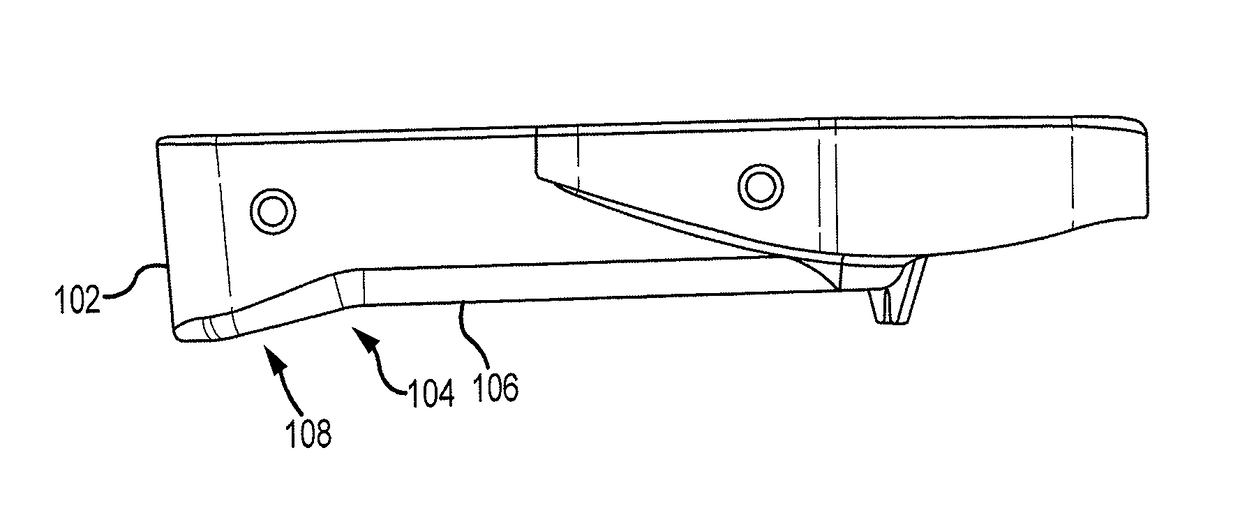
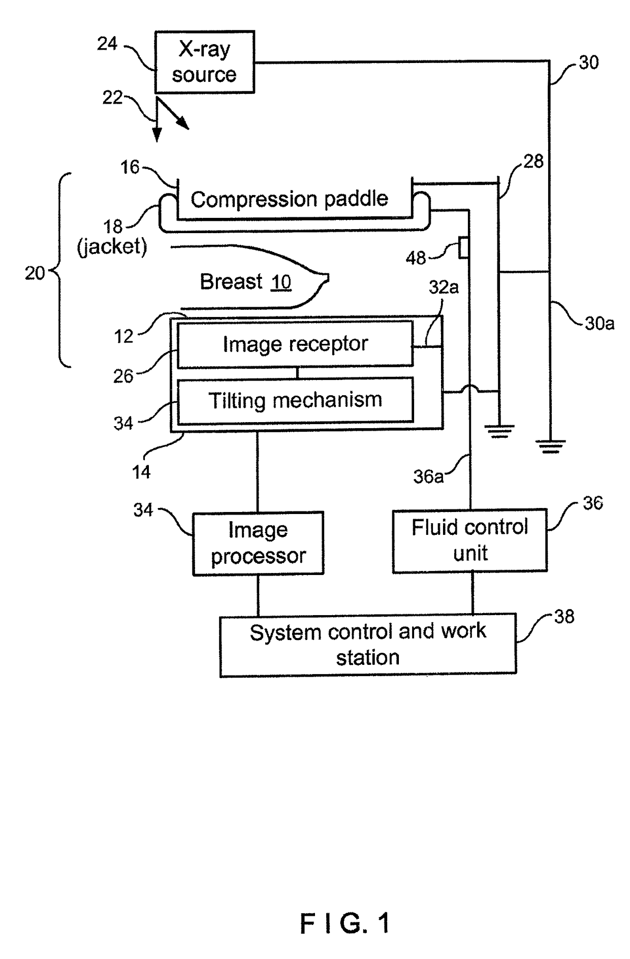
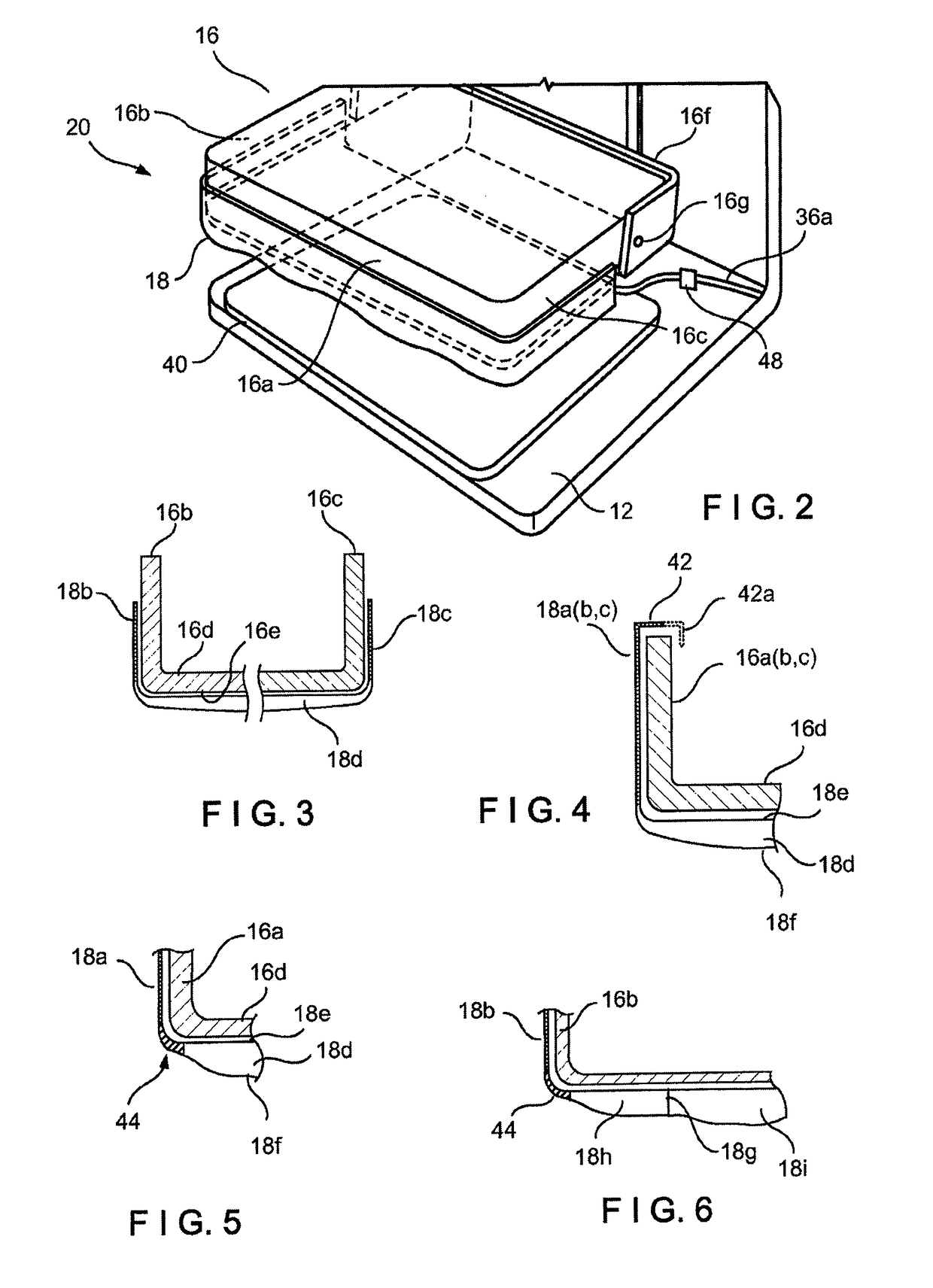
[0035]Referring to FIG. 1, a patient's breast 10 is immobilized for x-ray imaging between a breast platform 12 and a compression paddle 16. Platform 12 can be the upper surface of a housing 14. At least an underside of compression paddle 16 is covered with a non-rigid paddle jacket, such as, preferably, an inflatable paddle jacket 18. Platform 12 and paddle 16 form a breast immobilizer unit 20 that is in a path of an imaging beam 22 emanating from x-ray source 24. Beam 22 impinges on image receptor 26 that is in housing 14.

[0036]Immobilizer 20 and housing 14 are supported on an arm 28. X-ray source 24 is supported on an arm 30. For mammography, support arms 28 and 30 can rotate as a unit about an axis such as at 30a between different imaging orientations such as CC and MLO, so that the system can take a mammogram projection image Mp at each orientation. Image receptor 26 remains in place relative to...


PUM


Abstract

An x-ray breast imaging system comprising a compression paddle in which the compression paddle comprises a front wall and a bottom wall. The front wall is configured to be adjacent and face a chest wall of a patient during imaging and the bottom wall configured to be adjacent a length of a top of a compressed breast. The bottom wall extends away from the patient's chest wall, wherein the bottom wall comprises a first portion and a second portion such that the second portion is between the front wall and the first portion. The first portion is generally non- coplanar to the second portion, wherein the compression paddle is movable along a craniocaudal axis. The x-ray breast imaging system also comprises a non-rigid jacket releasably secured to the compression paddle, the non-rigid jacket positioned between the compression paddle and the patient.

Description

CROSS-REFERENCE TO RELATED APPLICATIONS[0001]This application is a National Stage Application of PCT / US2014 / 035334, filed Apr. 24, 2014which claims benefit of U.S. Provisional Patent Application No. 61 / 950,938, filed Mar. 11, 2014; and U.S. Provisional Patent Application No. 61 / 816,202, filed Apr. 26, 2013. The present application also claims the benefit under 35 U.S.C. §120 and is a continuation-in-part of U.S. patent application Ser. No. 13 / 679,446, filed Nov. 16, 2012, now U.S. Pat. No. 9,332,947, which claims the benefit under 35 U.S.C. §119 to U.S. Provisional Patent Application Ser. No. 61 / 561,620, filed Nov. 18, 2011. The disclosures of each of the foregoing applications are incorporated by reference herein in their entireties. To the extent appropriate, a claim of priority is made to each of the above disclosed applications.INTRODUCTION[0002]A significant patient concern in x-ray mammography and breast tomosynthesis is the discomfort the patient may feel when the breast is c...

Claims


Application Information

Patent Timeline
Patent Type & Authority Patents(United States)
IPC IPC(8): A61B6/02A61B6/04A61B6/00
CPCA61B6/0414A61B6/502A61B6/04A61B6/025
Inventor STANGO, TIMOTHY R.DEFREITAS, KENNETH F.SHAW, IANSTEIN, JAYJAMESON-MEEHAN, LYNNENIKLASON, LOREN
Owner HOLOGIC INC
Why Eureka
Try Eureka