
Self-adjusting pocket hole jig

a pocket hole and self-adjusting technology, applied in the field of pocket hole jigs, can solve the problems of poor design, ragged edges, high price, etc., and achieve the effect of simplifying the clamping mechanism and simplifying the selection of screws

Active Publication Date: 2017-10-10
PELKEY MICHAEL H
View PDF18 Cites 23 Cited by
  • Summary
  • Abstract
  • Description
  • Claims
  • Application Information

AI Technical Summary

Benefits of technology

The present invention is a pocket hole jig that has a unique design that allows it to automatically adjust to the thickness of the wood being used. It includes a one-piece base, a sliding carriage with a simple clamping mechanism, accurate drill stop assembly, and adjustable drill guides. The jig also has an adjustable side stop mechanism and a sealed dust port chamber. The main benefit of the invention is that it simplifies the process of creating pocket holes in wood, by accurately positioning them at the correct location for any wood thickness. Once set, the step drill stop collar requires no further adjustments within the clamp range of workpiece widths. Additionally, the jig makes screw selection easier, requiring only thickness measurement of the second workpiece, to which is added ½ inch for total screw length.

Problems solved by technology

Several jigs are commercially available, albeit costly, complex, and bulky.
Often complicated to use, some having a poor design generate holes with ragged edges.

Method used


Image

  • Self-adjusting pocket hole jig
  • Self-adjusting pocket hole jig
  • Self-adjusting pocket hole jig

Examples


Embodiment Construction

[0040]The self-adjusting pocket hole jig is disclosed herein with respect to exemplary embodiments. The embodiments are disclosed for illustration of the self-adjusting pocket hole jig and a manner of operation, and are not limiting except as defined in the appended claims.

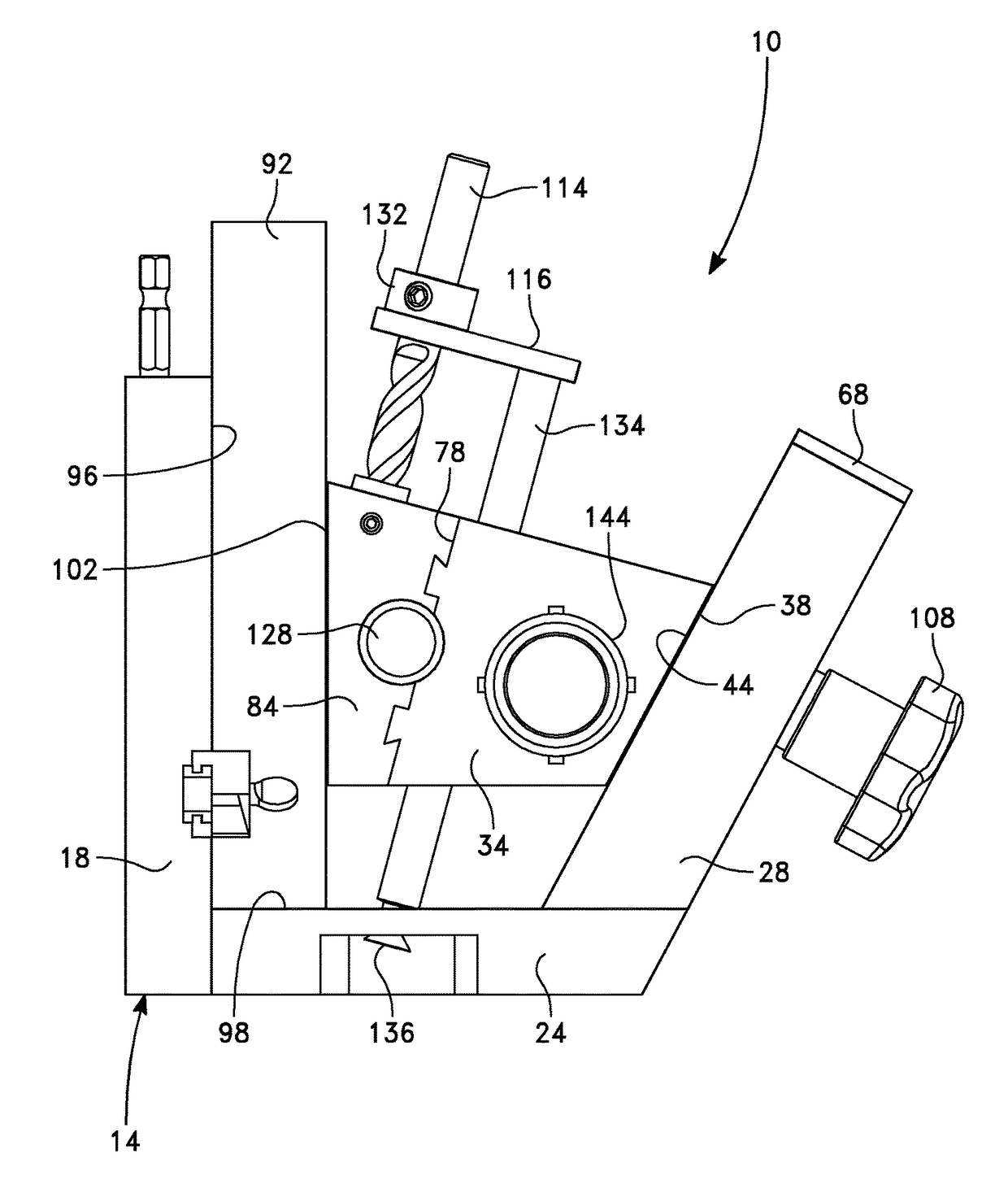
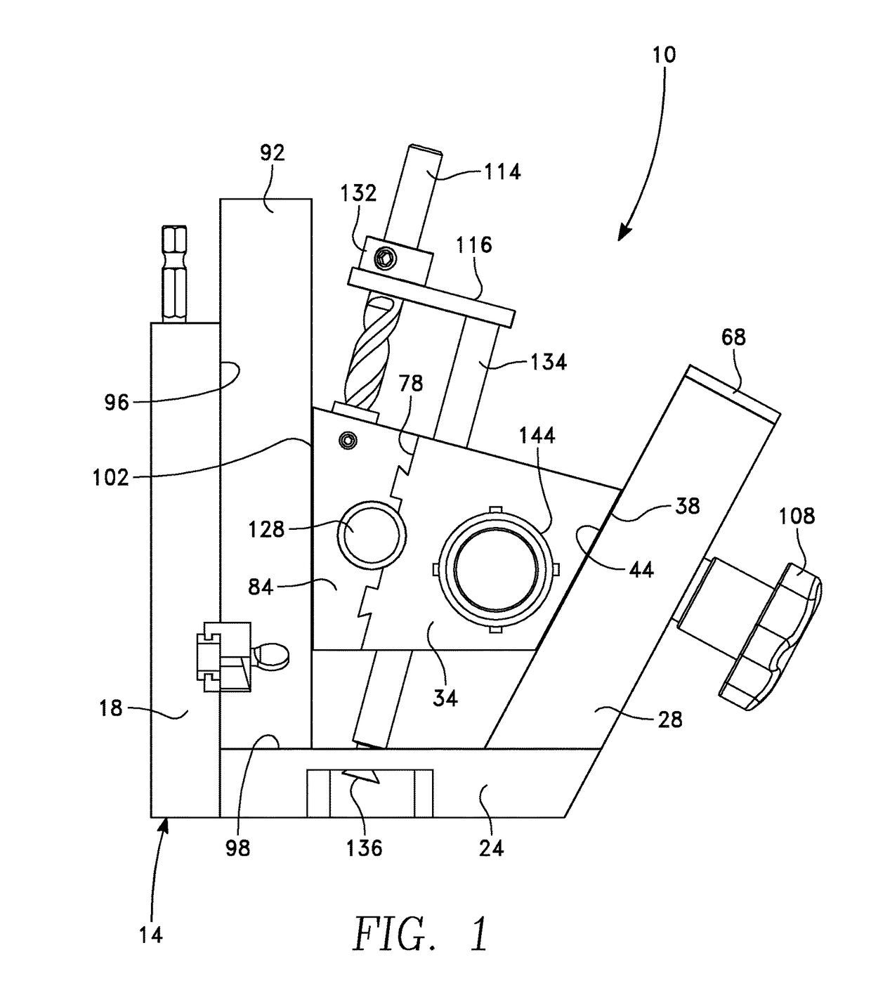
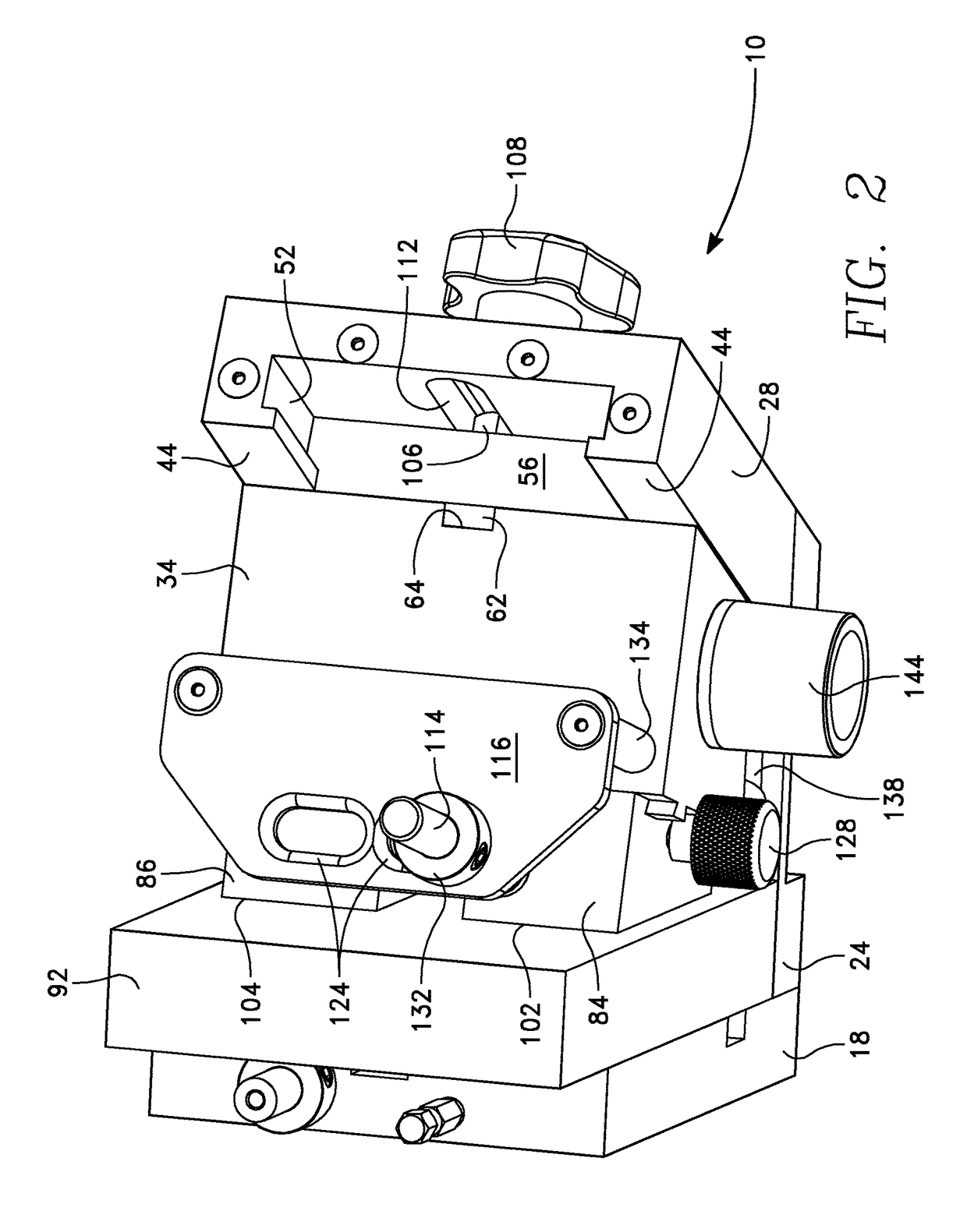
[0041]A pocket hole jig 10 in accordance with the present invention is shown in FIGS. 1 and 2, and the exploded view of FIG. 3. The pocket hole jig 10 includes a jig base 14 formed of three attached base members, a vertical member 18, a horizontal member 24, and an angled member 28. In a presently preferred embodiment a plurality of cavities for storage are provided within the vertical base 18, (a stored step drill and a stored driver are shown in FIGS. 1-3).

[0042]A carriage 34 travels along the angled base 28, a rear surface 38 slidably engaging the inclined front surface 44 of the angled base 28. A slide channel 52 formed in the angled base member (see FIG. 2) slidably receives a slide plate 56, the slide plate ...


PUM

PropertyMeasurementUnit
lengthaaaaaaaaaa
lengthaaaaaaaaaa
lengthaaaaaaaaaa

Abstract

A pocket hole jig utilizes a pair of adjustable drill guides attached at the front of a movable carriage to enable self-adjustment in pocket hole placement over a range of workpiece thicknesses. The carriage is slidably received on an angled base member and may be moved toward or away from a vertical base member used to support wooden workpieces. A locking mechanism retains the carriage in its adjusted position. The pair of drill guides are adjustably positioned towards or away from one another and relative to the pocket hole jig axis of symmetry, locating the pair of pocket hole drilling locations.

Description

RELATED APPLICATIONS[0001]The present application claims the benefit of priority under 35 USC §119(e) to U.S. Provisional Application No. 62 / 234,928, filed on Sep. 30, 2015, which is incorporated by reference herein for all that it contains.BACKGROUND OF THE INVENTION[0002]Field of the Invention[0003]The present invention relates to jig used to join two workpieces and, more particularly, to a pocket hole jig. More specifically, the present invention relates to a pocket hole jig that self-adjusts to correctly position a pair of pocket holes, symmetrically located about the centerline of the jig, over the clamp range of wood workpiece thicknesses.[0004]Description of the Related Art[0005]Pocket hole joinery is used extensively in woodworking as a quick and easy way to join two wood workpieces. A pocket hole is a pilot hole drilled at an angle in a first wood workpiece to align a screw for fastening to a second workpiece. A step drill creates a counterbored hole for the head of the poc...

Claims


Application Information

Patent Timeline
Patent Type & Authority Patents(United States)
IPC IPC(8): B23B47/28B23B49/00
CPCB23B47/287B23B49/003Y10T408/567B23B2260/0482B23B2247/10
Inventor PELKEY, MICHAEL H.
Owner PELKEY MICHAEL H
Learn More