Thermal spray assembly and method for using it

a technology of thermal spray and assembly, which is applied in the direction of plasma welding apparatus, coatings, electrical apparatus, etc., can solve the problems of material evaporation, plasma jet and be lost in the thermal spray process, tool body may be worn or corroded in use, etc., and achieve the effect of reducing the rate of mechanical wear and corrosion of the tool body in us

Active Publication Date: 2017-10-17
ELEMENT SIX GMBH
View PDF16 Cites 0 Cited by
  • Summary
  • Abstract
  • Description
  • Claims
  • Application Information

AI Technical Summary

Benefits of technology

[0033]In some examples, the precursor material is suitable for depositing a hard layer of material having hardness substantially greater than that of the steel comprised in the body. The deposited material may form a layer that is capable of reducing the rate of corrosion and or mechanical wear of the tool body in use.

Problems solved by technology

If the melting point of the precursor material is too low, there is a risk that material may evaporate while within the plasma jet and be lost to the thermal spray process.
In some examples, the tool body may be for some other tool or component at risk of being worn or corroded in use.

Method used


Image

  • Thermal spray assembly and method for using it
  • Thermal spray assembly and method for using it
  • Thermal spray assembly and method for using it

Examples


Embodiment Construction

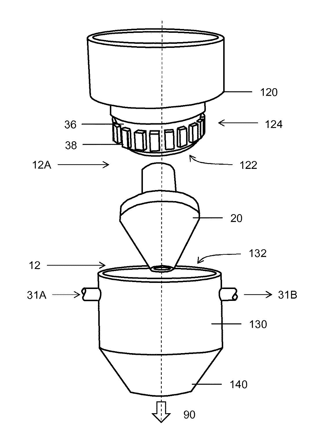
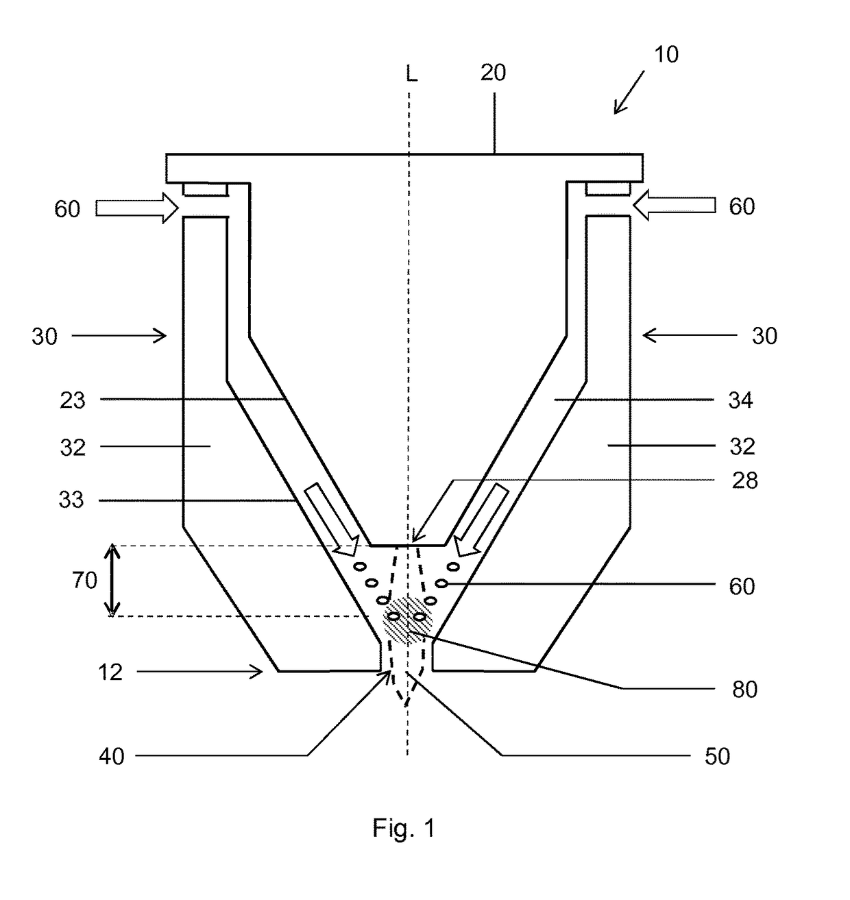
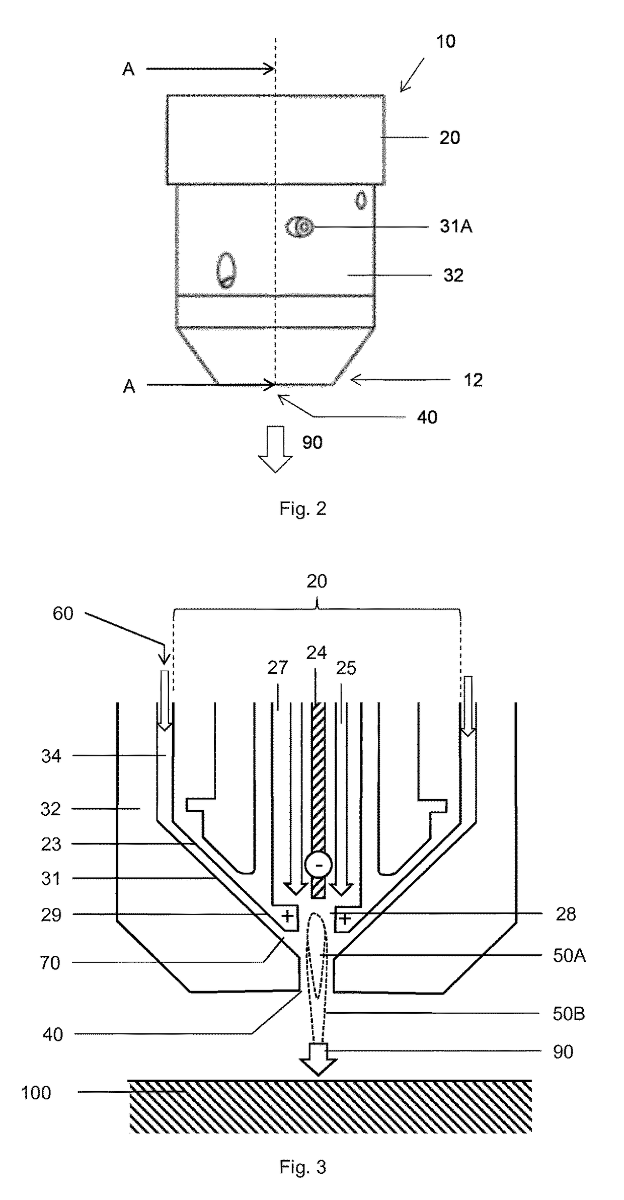
[0044]With reference to FIG. 1, an example thermal spray assembly 10 (shown in the assembled state, as a thermal spray device 10) for transforming precursor material 60 into a layer of deposited material joined to a substrate body (not shown); comprising a plasma torch 20 and a feeder mechanism 30, configured such that the plasma torch 20 is capable of producing a plasma jet into a plasma region 50, to be occupied by the plasma jet and to extend from the plasma nozzle 28 in use. The feeder mechanism 30 is capable of guiding the precursor material 60 into the plasma region 50. The feeder mechanism 30 is capable of providing a feeder orifice 70 when in an open condition (as sown in FIG. 1) and comprises a guide chamber 34 and a moveable guide mechanism 32. The feeder mechanism 30 is configured such that the guide chamber 34 is capable of guiding the precursor material 60 to the feeder orifice 70, through which the precursor material 60 can move from the guide chamber 34 and enter the ...


PUM

PropertyMeasurementUnit
cone anglesaaaaaaaaaa
axial displacementaaaaaaaaaa
phase liquidus temperatureaaaaaaaaaa

Abstract

A thermal spray assembly (10) for transforming precursor material (60) into a layer of deposited material joined to a substrate body. A plasma torch produces a plasma jet from a plasma nozzle (28) and a feeder mechanism (30) guides the precursor material into the plasma jet in use and is capable of providing a feeder orifice when in an open condition. The feeder mechanism (30) is provided with a distribution chamber configured for guiding moving precursor material azimuthally around the plasma torch, a plurality of deflector structures (38) configured for deflecting the precursor material (60) from the distribution chamber and guiding it into a guide chamber configured for guiding the precursor material (60) to the plasma jet in use.

Description

CROSS REFERENCE TO RELATED APPLICATIONS[0001]This application is the U.S. national phase of International Application No. PCT / EP2015 / 061396 filed on May 22, 2015, and published in English on Dec. 3, 2015 as International Publication No. WO 2015 / 181076 A1, which application claims priority to United Kingdom Patent Application No. 1409693.7 filed on May 31, 2014, the contents of all of which are incorporated herein by reference.TECHNICAL FIELD[0002]This disclosure relates generally to thermal spray assemblies and methods of using them to deposit material on a substrate, particularly but not exclusively for depositing a hard layer onto a steel body, such as a tool for mining, earth boring or road milling.BACKGROUND ART[0003]International patent application, publication number WO / 2013 / 178550 discloses a method for making a construction comprising a steel substrate body coated with a layer of relatively harder material. The method may include providing a plurality of granules comprising ...

Claims


Application Information

Patent Timeline
Patent Type & Authority Patents(United States)
IPC IPC(8): B23K10/00C23C4/134H05H1/42B05B7/22B05D1/02
CPCB05B7/226B05D1/02C23C4/134H05H1/42B05B15/18
Inventor KRENN, ANDREAS
Owner ELEMENT SIX GMBH
Why Eureka
Try Eureka