Geodesic structure forming systems and methods

a technology of geodesic structure and forming system, which is applied in the field of geodesic structure forming system and method, can solve the problems of time and labor, complex process of locating and assembling such a large number of separate and distinct parts, and time-consuming and labor-intensive assembly of a semi-monocoque structur

Active Publication Date: 2017-10-17
THE BOEING CO
View PDF27 Cites 69 Cited by
  • Summary
  • Abstract
  • Description
  • Claims
  • Application Information

AI Technical Summary

Benefits of technology

[0019]The mandrel may include a plurality of pads that are moveable between deployed and retracted positions. The pads securely retain the framework and the covering skin in the deployed position, and allow the framework and the covering skin to be removed from the mandrel in the retracted position.

Problems solved by technology

As can be appreciated, the process of forming the fuselage section is time and labor intensive.
As such, the process of locating and assembling such a large number of separate and distinct parts is complicated, time-consuming, and labor-intensive.
Due to the repetitive nature of such an assembly process, and the small tolerances involved, the assembly of a semi-monocoque structure is time and labor intensive.

Method used


Image

  • Geodesic structure forming systems and methods
  • Geodesic structure forming systems and methods
  • Geodesic structure forming systems and methods

Examples


Embodiment Construction

[0041]The foregoing summary, as well as the following detailed description of certain embodiments will be better understood when read in conjunction with the appended drawings. As used herein, an element or step recited in the singular and preceded by the word “a” or “an” should be understood as not necessarily excluding the plural of the elements or steps. Further, references to “one embodiment” are not intended to be interpreted as excluding the existence of additional embodiments that also incorporate the recited features. Moreover, unless explicitly stated to the contrary, embodiments “comprising” or “having” an element or a plurality of elements having a particular property may include additional elements not having that property.

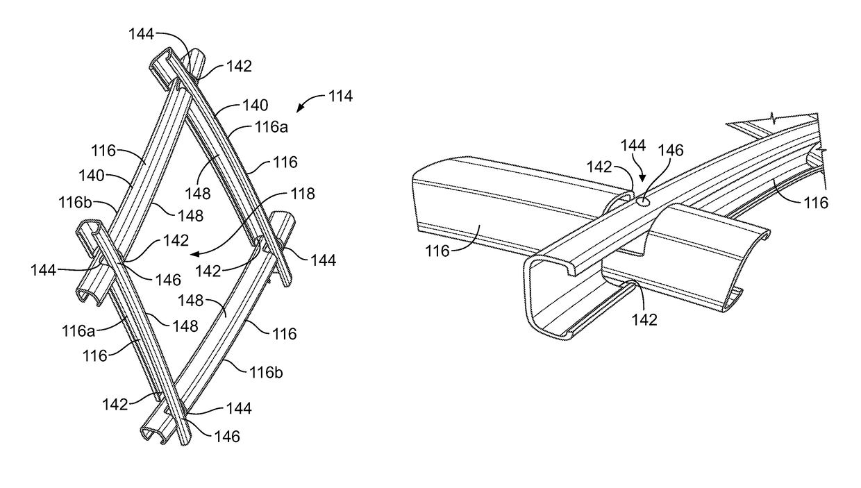
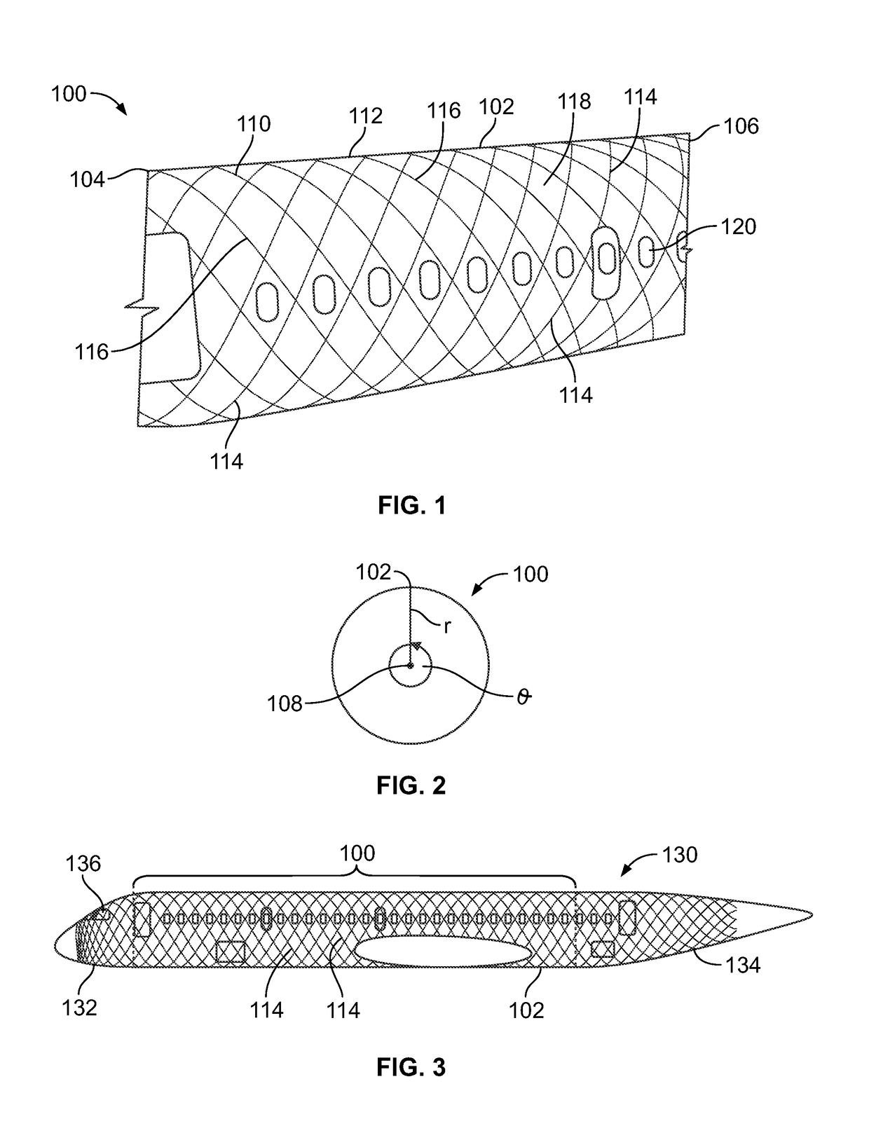
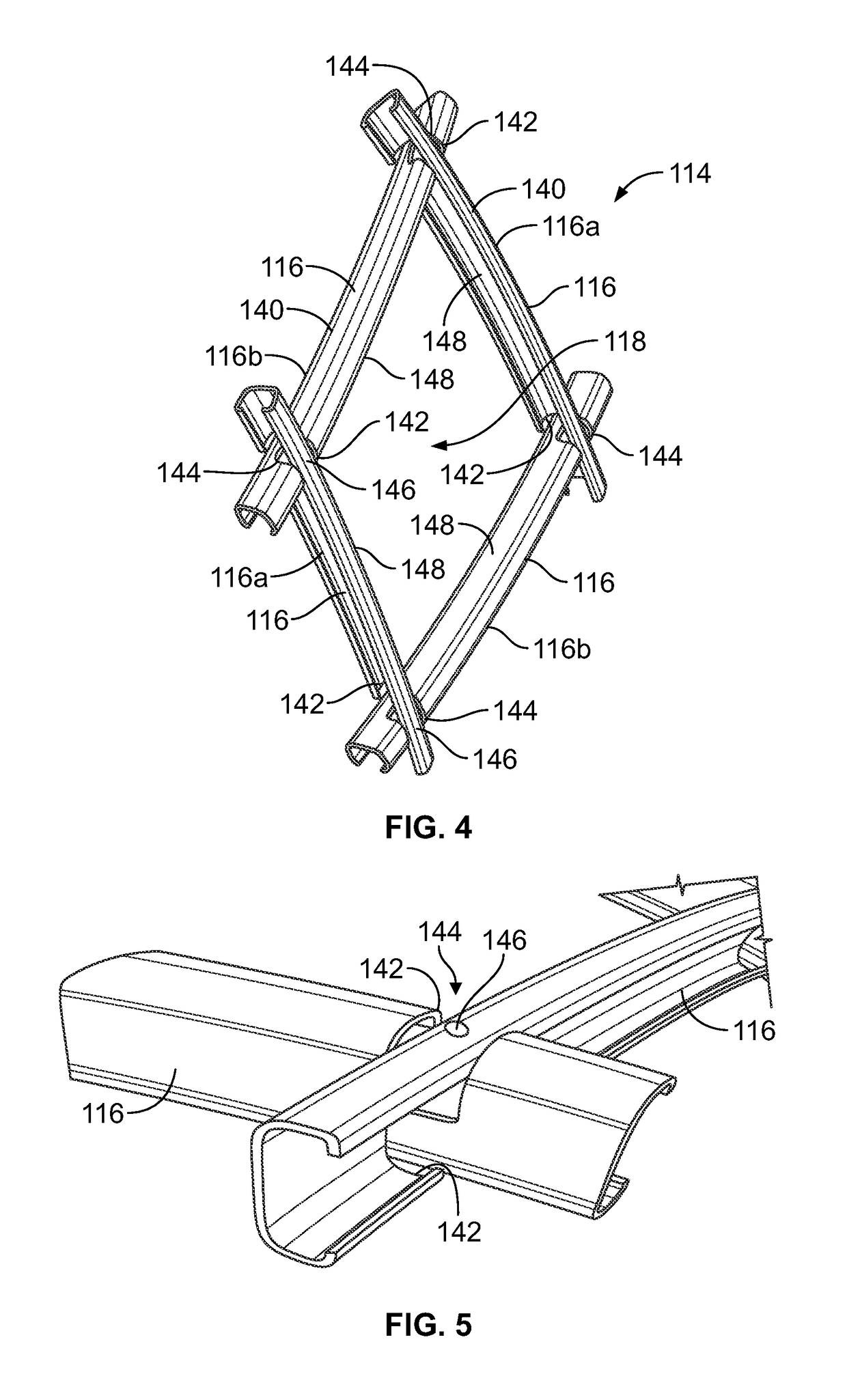
[0042]Certain embodiments of the present disclosure provide systems and methods of manufacturing a portion of a vehicle. For example, certain embodiments of the present disclosure may be used to form a constant section of a fuselage of an aircraft. The...


PUM

PropertyMeasurementUnit
structureaaaaaaaaaa
constant cross-sectional radiusaaaaaaaaaa
sizeaaaaaaaaaa

Abstract

A system and method determine a size and a shape for identical geodesic modules that are used to form a structure. The system and method may include analyzing input data regarding a size and a shape of the structure to be formed, and determining the size and the shape for each of the identical geodesic modules based on the size and the shape of the structure to be formed. The structure may include a framework including the identical geodesic modules. Each of the geodesic modules has a size and a shape that are the same as all of the other of the geodesic modules. A forming system and method position a framework and a covering skin of the structure in relation to a mandrel, and drill and rivet the framework to the covering skin with a plurality of operating heads.

Description

FIELD OF THE DISCLOSURE[0001]Embodiments of the present disclosure generally relate to systems and methods for manufacturing a tubular structure, such as a portion of a fuselage of a vehicle, and, more particularly, to systems and methods for forming (for example, assembling) a constant section of a fuselage of a vehicle.BACKGROUND OF THE DISCLOSURE[0002]Various vehicles are formed through numerous components. For example, a fuselage of an aircraft may be formed through various stringers, frames, bulkheads, keel beams, and the like that are secured together through numerous fasteners, such as rivets. As can be appreciated, the process of forming the fuselage section is time and labor intensive.[0003]Geodesic airframes have also been used to form fuselages. Known geodesic airframes have a variable (that is, non-constant) cross-section throughout. Accordingly, every separate and distinct element of known geodesic airframes has a unique and distinct shape. Consequently, a large number ...

Claims


Application Information

Patent Timeline
Patent Type & Authority Patents(United States)
IPC IPC(8): B23P23/04B23B41/00B21J15/14B64C1/08B21J15/30B64F5/10B64C1/12
CPCB23B41/00B21J15/142B21J15/30B64F5/10B23B2215/04B64C1/08B64C1/12Y10T29/49616Y10T29/49622Y10T29/49867Y10T29/49943Y10T29/49947Y10T29/49956
Inventor GOLSHANY, SINAAHN, JUNGHYUNALDERKS, DEREKERICKSON, TODD WILLIAM
Owner THE BOEING CO
Why Eureka
Try Eureka