Pneumatic tank trailer

a technology of pneumatic tank trailer and trailer, which is applied in the direction of tank vehicles, loading/unloading vehicle arrangments, transportation items, etc., can solve the problems of reducing the fuel efficiency of the vehicle towing the pneumatic tank trailer, creating turbulence, and creating drag, so as to improve the aerodynamic efficiency

Active Publication Date: 2017-10-17
RACEHORSE INVESTMENTS LLC
View PDF83 Cites 30 Cited by
  • Summary
  • Abstract
  • Description
  • Claims
  • Application Information

AI Technical Summary

Benefits of technology

[0004]A pneumatic tank trailer with improved aerodynamic efficiency is described. A pneumatic tank trailer with several functional improvements is described.

Problems solved by technology

The front region of the conventional pneumatic tank trailer faces generally perpendicular to the direction of travel, and the front region is exposed to the oncoming air and creates turbulence, as the air strikes against various plumbing fittings and structural members positioned at the front of the trailer.
When the trailer is moving, wind and air strike the front of the trailer, plumbing, fittings, and pipes thus creating turbulence and drag.
This turbulent air is directed about the trailer, resulting in reduced fuel efficiency for the vehicle towing the pneumatic tank trailer.
The external vertical ribs cause wind resistance and drag, and thus reduce fuel efficiency.

Method used


Image

  • Pneumatic tank trailer
  • Pneumatic tank trailer
  • Pneumatic tank trailer

Examples


Embodiment Construction

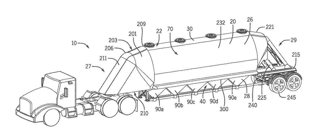
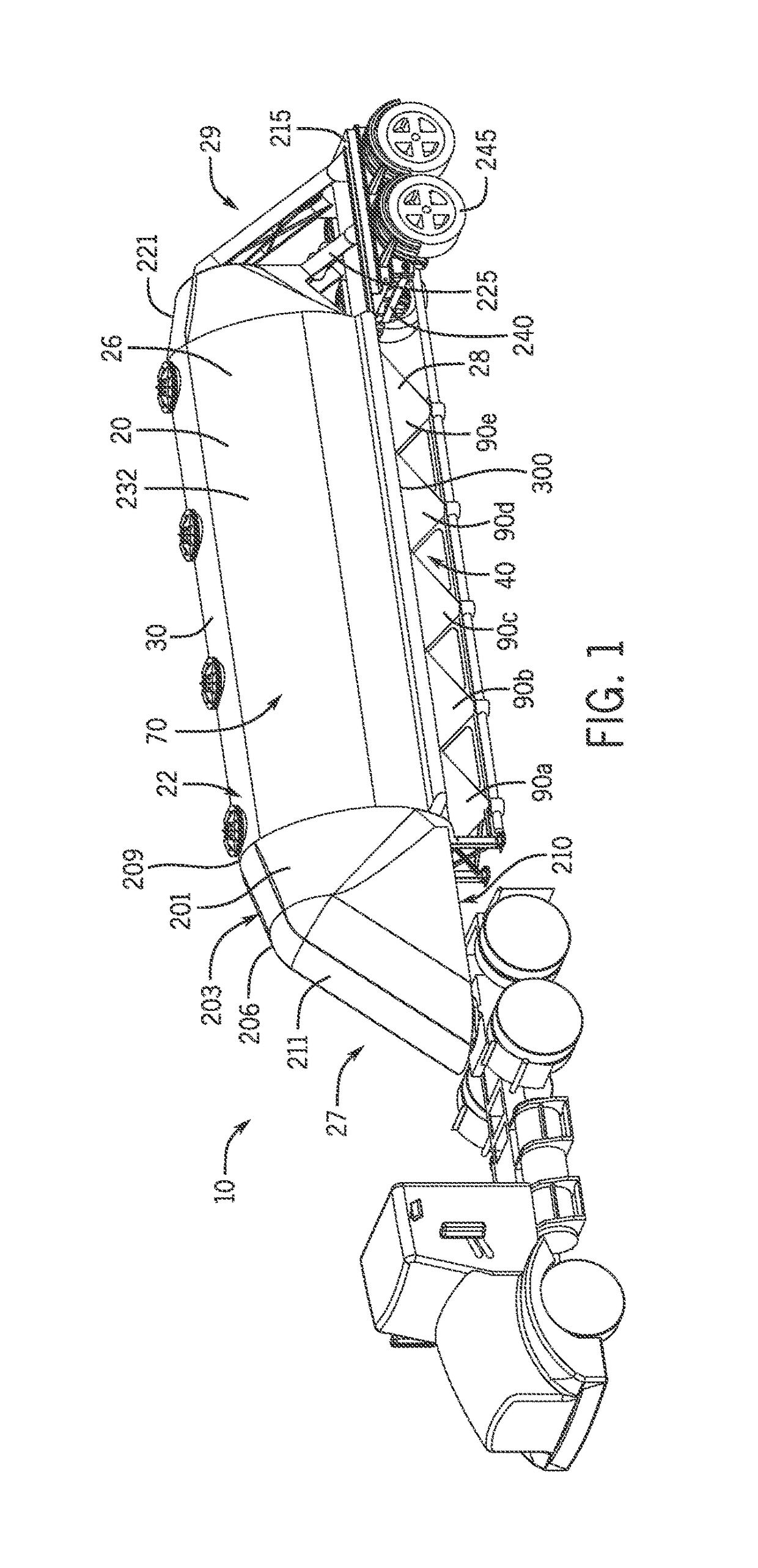
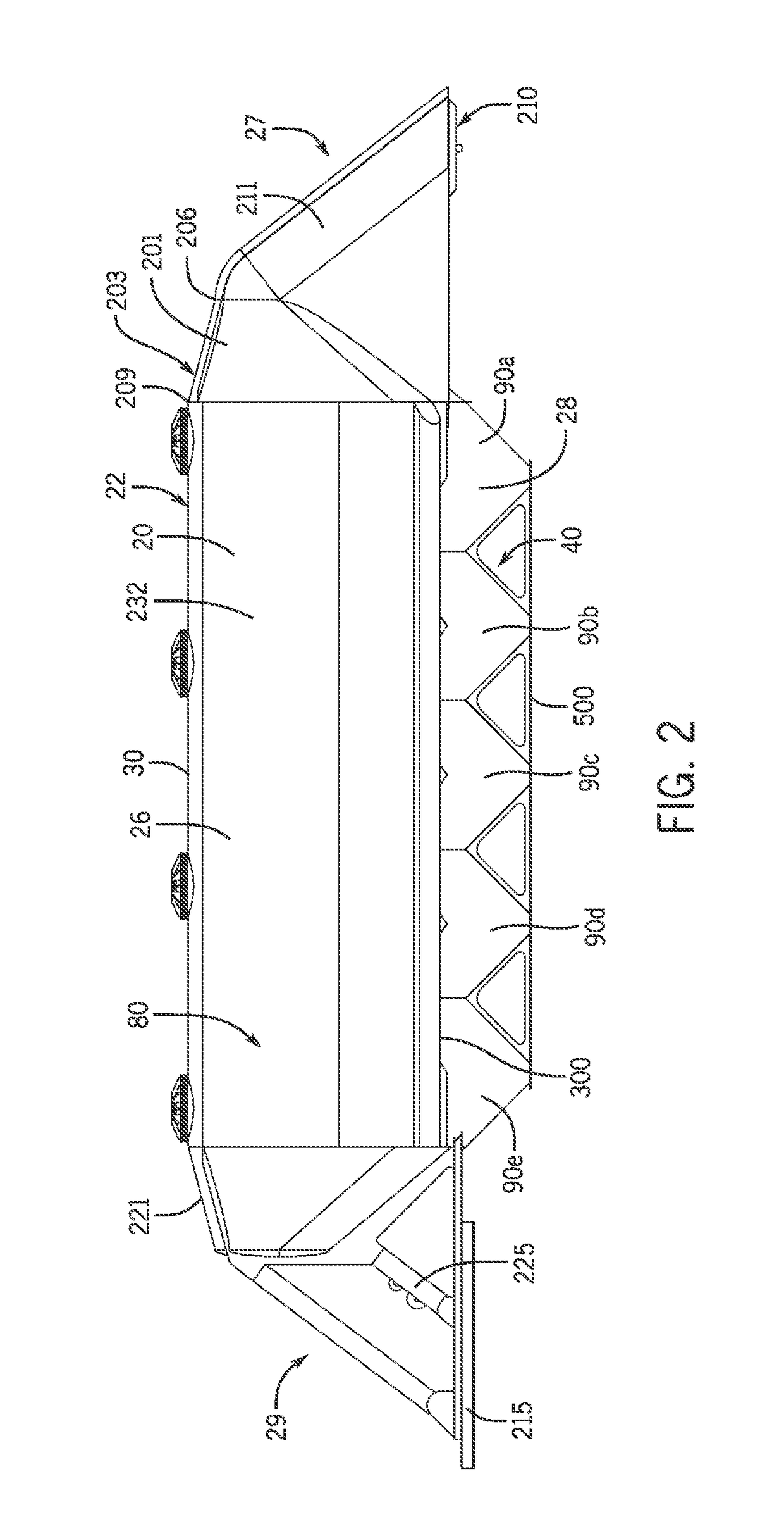
[0042]A pneumatic tank trailer 10 and components thereof are shown in FIGS. 1-14. The pneumatic tank trailer 10 includes a tank 20 that defines an interior volume 25. The tank 20 is the holding section of the pneumatic tank trailer 10 that can be pressurized. The pneumatic tank trailer 10 includes a front end portion 27 that is proximate a king pin of the pneumatic trailer 10. The king pin connects the pneumatic tank trailer 10 to the tractor or other towing vehicle. The pneumatic tank trailer 10 includes a rear end portion 29 proximate rear wheels 245 of the pneumatic tank trailer 10. The interior volume 25 may be pressurized to facilitate unloading of the dry bulk material.

[0043]The pneumatic tank trailer 10 includes an aerodynamic shape that improves fuel efficiency. The pneumatic tank trailer 10 may be designed for traveling over one million miles during its lifetime, and aerodynamic efficiency results in significant fuel costs savings. As described below, the pneumatic tank tra...


PUM


Abstract

A pneumatic tank trailer includes a carriage and a tank supported on the trailer that can selectively discharge fluidizable material through hoppers of the tank. A nose portion of the trailer has a generally conical shape. The nose portion has a top that slopes downward and sides that taper inward as it extends forward. A cross-sectional center point of a front end of the nose portion is lower than a cross-sectional center point of a rear end of the nose portion along the height of the trailer. The length of the nose portion is at least 15% of the length of the trailer. Adjacent hoppers intersect at hopper crotches. The hopper crotches have short heights and the hoppers are arranged relatively close together.

Description

CROSS REFERENCE TO RELATED APPLICATION[0001]This application is a continuation-in-part of U.S. patent application Ser. No. 14 / 957,085, filed Dec. 2, 2015, which is a continuation-in-part of U.S. patent application Ser. No. 14 / 515,708, filed Oct. 16, 2014, which claims the benefit of U.S. Provisional Patent Application No. 61 / 891,630 filed Oct. 16, 2013. This application also claims the benefit of U.S. Provisional Patent Application No. 62 / 148,158, filed Apr. 15, 2015. Each of these applications is hereby incorporated by reference in its entirety.FIELD OF INVENTION[0002]The present invention relates to a pneumatic tank trailer.BACKGROUND OF INVENTION[0003]Pneumatic tank trailers are commonly used to haul a variety of dry bulk materials, such as, for example, lime products, cement, fly ash, food products, etc. The pneumatic tank trailers include a tank that receives the dry bulk materials. The tank typically includes one or more hoppers positioned along a bottom portion of the tank fo...

Claims


Application Information

Patent Timeline
Patent Type & Authority Patents(United States)
IPC IPC(8): B60P3/22B60P3/24B62D35/00B62D63/08
CPCB62D35/001B60P3/2205B62D63/08B60P3/243B60P3/2245B60P1/56B60P3/2225
Inventor BEELMAN, III, FRANK J.SMITH, DAVID
Owner RACEHORSE INVESTMENTS LLC
Why Eureka
Try Eureka