Unlock instant, AI-driven research and patent intelligence for your innovation.
Triboelectric generators and sensors
What is Al technical title?
Al technical title is built by PatSnap Al team. It summarizes the technical point description of the patent document.
a generator and triboelectric technology, applied in the direction of machines/engines, charging/discharging current/voltage regulation, instruments, etc., can solve the problems of triboelectric nanogenerators with limited power output, largely ignored triboelectric effect as an energy source, and charge imbalan
Active Publication Date: 2017-10-17
GEORGIA TECH RES CORP
View PDF6 Cites 30 Cited by
Summary
Abstract
Description
Claims
Application Information
AI Technical Summary
This helps you quickly interpret patents by identifying the three key elements:
Problems solved by technology
Method used
Benefits of technology
Problems solved by technology
However, most triboelectric nanogenerators have limited power output.
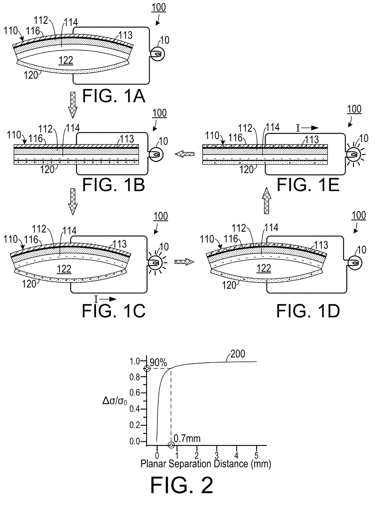
If the two materials are separated from each other, a charge imbalance will occur.
This charge imbalance gives rise to what is sometimes referred to as “static electricity.” The term “static” in this case is somewhat deceptive, as it implies a lack of motion when in reality motion is necessary for charge imbalances to flow.
However, the triboelectric effect has been largely ignored as an energy source for electricity.
Some electrostatic micro-generators have been developed and used in research relating to micro-electro-mechanical systems (MEMS), but such designs rely on an extra voltage source to charge electrode plates instead of harnessing triboelectric effect, leading to complicated structures and fabrication processes.
Previously demonstrated triboelectric generators require periodic contact and vertical separation of two materials that have opposite triboelectric polarities, making it only applicable to harvest energy from intermittent impact or shock.
Such systems typically include a cavity with a constantly changing volume, which makes packaging difficult and limits applications in atmospheres with high humidity, corrosive chemicals or gases, and in water or other liquids.
Method used
Image
Click on the blue label to locate the original text in one second.
Reading with bidirectional positioning of images and text.
Examples
Embodiment Construction
[0048]A preferred embodiment of the invention is now described in detail. Referring to the drawings, like numbers indicate like parts throughout the views. Unless otherwise specifically indicated in the disclosure that follows, the drawings are not necessarily drawn to scale. As used in the description herein and throughout the claims, the following terms take the meanings explicitly associated herein, unless the context clearly dictates otherwise: the meaning of “a,”“an,” and “the” includes plural reference, the meaning of “in” includes “in” and “on.”
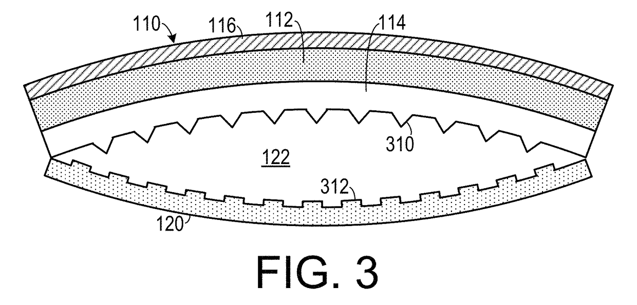
[0049]As shown in FIG. 1A, one embodiment of a triboelectric generator 100 includes a first contact charging member 110 that has a first substrate material layer 112, which could include poly(4,4′-oxydiphenylene-pyromellitimide) (which is sold under the trademark “Kapton”), adjacent to a second substrate material layer 113, which can include a material such as SiO2. The first contact charging member 110 also includes a first contact la...
PUM
Property
Measurement
Unit
size
aaaaa
aaaaa
open-circuit voltage
aaaaa
aaaaa
short-circuit current
aaaaa
aaaaa
Abstract
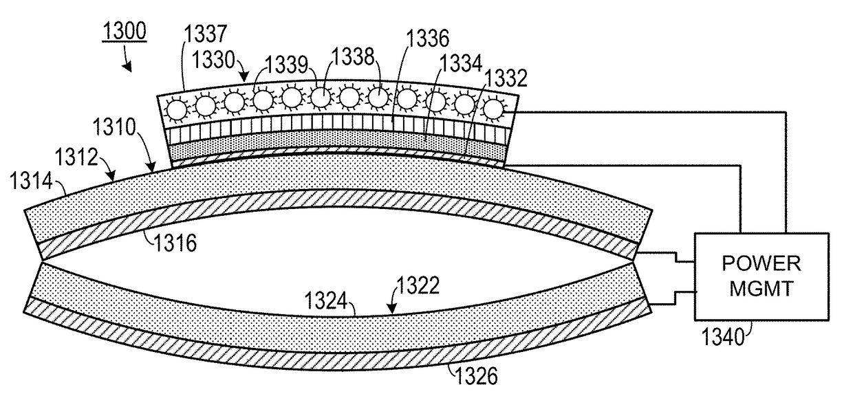
A triboelectric power system includes a triboelectric generator, a rechargeable energy storage unit and a power management circuit. The rechargeable energy storage unit is associated to the triboelectric generator. The power management circuit is configured to receive an input current from the triboelectric generator and to deliver an output current corresponding to the input current to the rechargeable battery so that the output current has a current direction and a voltage that will recharge the rechargeable battery.
Description
CROSS-REFERENCE TO RELATED APPLICATION(S)[0001]This application claims the benefit of the following U.S. Provisional Patent Application Ser. Nos. 61 / 859,808, filed Jul. 30, 2013; 61 / 863,627, filed Aug. 8, 2013; 61 / 859,843, filed Jul. 30, 2013; and 61 / 897,447, filed Oct. 30, 2013, the entirety of each which is hereby incorporated herein by reference. This application is a continuation-in-part of, and claims the benefit of, U.S. patent application Ser. No. 14 / 032,864, filed Sep. 20, 2013, which is a non-provisional of 61 / 704,138, filed Sep. 21, 2012 and 61 / 754,992, filed Jan. 22, 2013, the entirety of each of which is hereby incorporated herein by reference. This application is also a continuation-in-part of, and claims the benefit of, U.S. patent application Ser. No. 14 / 189,656, filed Feb. 25, 2014, which is a non-provisional of 61 / 771,371, filed Mar. 1, 2013, the entirety of each of which is hereby incorporated herein by reference.STATEMENT OF GOVERNMENT INTEREST[0002]This invention...
Claims
Application Information
Patent Timeline
Application Date:The date an application was filed.
Publication Date:The date a patent or application was officially published.
First Publication Date:The earliest publication date of a patent with the same application number.
Issue Date:Publication date of the patent grant document.
PCT Entry Date:The Entry date of PCT National Phase.
Estimated Expiry Date:The statutory expiry date of a patent right according to the Patent Law, and it is the longest term of protection that the patent right can achieve without the termination of the patent right due to other reasons(Term extension factor has been taken into account ).
Invalid Date:Actual expiry date is based on effective date or publication date of legal transaction data of invalid patent.

