
Method to produce a rod tag and tag produced by the method

a production method and rod technology, applied in the field of rod tags, can solve the problems of increasing the length of the rod, reducing the performance of the device, reducing the read range, and increasing the time consumption of the device and the necessary production process, so as to achieve the effect of prolonging the read range and not reducing the performan

Active Publication Date: 2017-10-24
ASSA ABLOY AB
View PDF7 Cites 0 Cited by
  • Summary
  • Abstract
  • Description
  • Claims
  • Application Information

AI Technical Summary

Benefits of technology

The invention proposes a method and a rod tag that are more efficient than previous methods and devices. The new method allows for longer read ranges and smaller tag sizes without compromising performance. The technical effect of using a pure symmetrical magnetic core simplifies the process and eliminates the need for orientation.

Problems solved by technology

A drawback of the classical rod tag configurations as disclosed in the above prior art is that the chip is positioned at the extremity of the rod, adding its own length to the total tag length.
A solution is given in U.S. Pat. No. 7,825,869 but here the rod has to be modified which has a consequence on its symmetry and renders its handling more difficult.
As mentioned previously, this known device has the disadvantage of a non-symmetrical ferrite core which implies in addition that a manufacturing step is necessary to shape the core and has the consequence of a loss of material.
This device and the necessary production process is therefore time consuming and more expensive.

Method used


Image

  • Method to produce a rod tag and tag produced by the method
  • Method to produce a rod tag and tag produced by the method
  • Method to produce a rod tag and tag produced by the method

Examples


Embodiment Construction

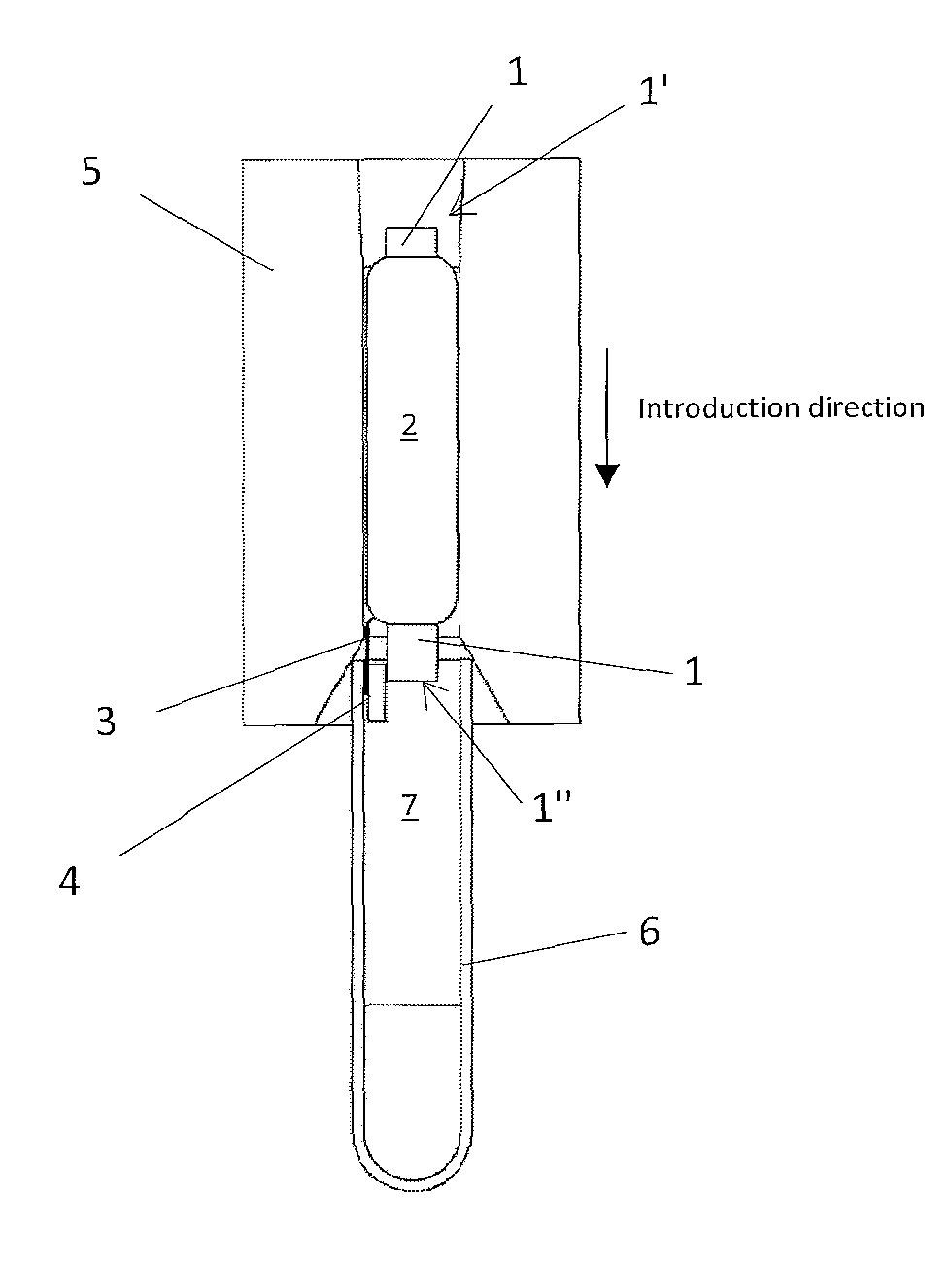
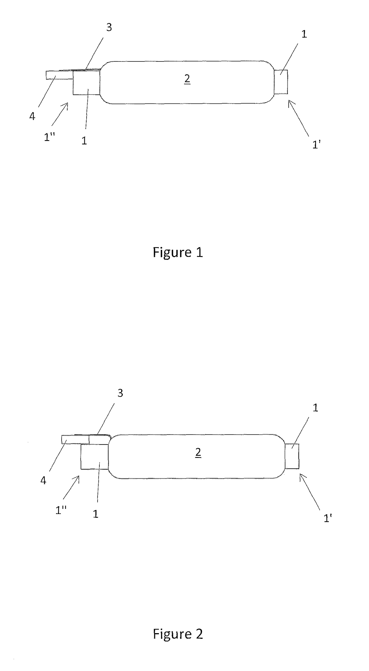
[0038]An idea of the present invention is to take advantage of the small size of the chip to place it in a free space without specifically shaping the rod forming the magnetic core. Accordingly, the core has a simple and pure cylindrical shape not necessitating some additional shaping steps as in the prior art. This saves time and material (and is therefore cheaper). In addition, this also avoids positioning constraints linked to the shape of the magnetic core as in the prior art. There is no need any more to hold it in a certain known position to ensure that the chip is placed in the space provided in the core as in U.S. Pat. No. 7,825,869 and US 2011 / 0259965 for example.

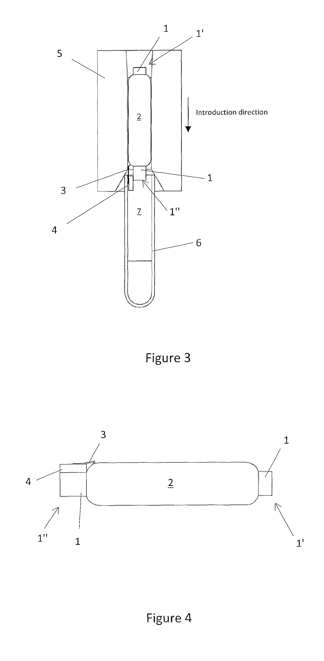
[0039]Further, the present invention takes advantage of the presence of stabilizing material (for example epoxy or any other suitable material) in the encapsulating means (for example a glass tube) to displace, for example push, the chip in its proper final position when introducing the tag in the encapsulating mea...


PUM

PropertyMeasurementUnit
cylindrical shapeaaaaaaaaaa
frictionaaaaaaaaaa
magneticaaaaaaaaaa

Abstract

A method to produce a rod tag and tag produced according to the method, wherein the method comprises at least the steps of:providing a magnetic core having a cylindrical shape and two end,winding a wire around said core to form an antenna,positioning in longitudinal extension a chip at one of the ends of said rod where the wound wire ends terminates,bonding said wire ends to contacts of said chip,displacing said bonded chip at least partially on said end of said rod, andintroducing said core with said wire and said chip in an encapsulating means containing a stabilizing material, whereby the chip is further positioned on said end by the friction between said chip and said material during introduction.

Description

CROSS REFERENCE TO RELATED APPLICATIONS[0001]This application claims the benefit of European Patent Application No. 12151321.2 filed Jan. 16, 2012, the disclosure of which is incorporated herein by reference.TECHNICAL FIELD[0002]The present invention concerns the field of rod tags comprising a ferrite rod core with a wound antenna around said rod core and more specifically the method used to produce such a tag.BACKGROUND ART[0003]Rod tags are well known RFID devices which usually comprise a ferrite rod around which a wire is wound to form an antenna and the antenna is connected then to a chip, thus forming the tag. Typically, such tags are encapsulated in a glass or synthetic casing to form the finished product.[0004]The technology of fabricating such rod tags is well known in the art. Prior art documents disclose in particular the step to bond the extremity of the winded wire (antenna) directly on the pads of a RFID chip: this is also called direct bonding.[0005]Prior art documents...

Claims


Application Information

Patent Timeline
Patent Type & Authority Patents(United States)
IPC IPC(8): H01Q7/08H05K13/00H01Q7/06H01Q1/42H01Q1/40H01Q1/22
CPCH01Q7/08H01Q1/2225H01Q1/40H01Q7/06H05K13/0023H01Q1/42Y10T29/49018H05K13/00
Inventor MEILLAND, ANDRESULIGOJ, ERICROBADEY, JEAN-MIGUELDEFFERRARD, JOELMONNARD, PATRICKBIELMANN, MARC
Owner ASSA ABLOY AB
Learn More