
Battery failure venting system

a battery failure and venting system technology, applied in the field of battery failure venting system, can solve the problems of dangerous battery operation to identify an overcharge condition, inability to distinguish between an overcharged battery with internal failure and a battery that is operating normally, and inability to discharge hydrogen

Inactive Publication Date: 2017-10-31
EL-SIGHT LTD
View PDF13 Cites 21 Cited by
  • Summary
  • Abstract
  • Description
  • Claims
  • Application Information

AI Technical Summary

Benefits of technology

The invention is about protecting battery packs from overheating and potentially causing a fire. It's a system that uses a thermally shielded compartment with a non-burning panel that can still get very hot and cause an exhaust opening. This prevents any fire from spreading and keeps the battery pack running.

Problems solved by technology

Unfortunately, prior to a battery being discharged in operation, typical battery condition monitors are unable to distinguish between an overcharged battery with internal failure and a battery that is operating normally.
Requiring a battery to be in operation to identify an overcharge condition is dangerous for a variety of reasons.
For example, when operating, a battery with an overcharge condition can be strongly discharged, leading to off-gassing of hydrogen, overheating or fire.
Battery fires in vehicles (e.g., aircraft) are a major risk where high-energy density volatile battery chemistries are used.
Fire suppression systems used in larger vehicles may not be appropriate for smaller vehicles.
For example, fire suppression systems (e.g., engine bottles, compressed gas or foam) used in large scale aircraft are not appropriate to smaller aircraft, which cannot afford the mass overhead.
Battery fires are especially problematic in vehicles (e.g., aircraft) where large numbers of volatile batteries are stored in close proximity.
Failure of a single battery may result in release of hot combustion gasses into a battery compartment, leading to combustion of multiple, and potentially all of the, batteries in the battery compartment.
Combustion of a sufficient number of batteries can be lead to vehicle (e.g., aircraft) loss.

Method used


Image

  • Battery failure venting system
  • Battery failure venting system
  • Battery failure venting system

Examples


Embodiment Construction

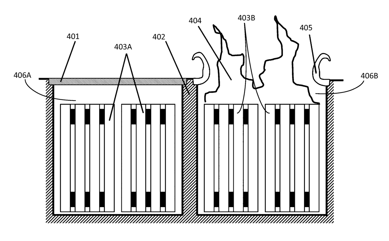
[0012]The present invention extends to methods, systems, devices, apparatus, and computer program products for protecting against runaway thermal failure of a battery pack. An arrangement of batteries is housed in a thermally shielded compartment. The thermally shielded compartment includes a heat sensitive but non-burning exterior panel. Heat buildup within the compartment cause the exterior panel to thermally react in a manner that creates an exhaust opening without burning. As such, a power system can continue operation without risk of internal fire propagation.

[0013]Embodiments of the invention include a passive device for (potentially automatically) venting flames, hot gases, and combustion products from within a container for batteries. A container or network of containers (with adjoining edges or entirely separate) isolates batteries or sets of batteries from one another other. Thermo-sensitive panel covers seal one or more vent ports (i.e., openings) of each container from o...


PUM


Abstract

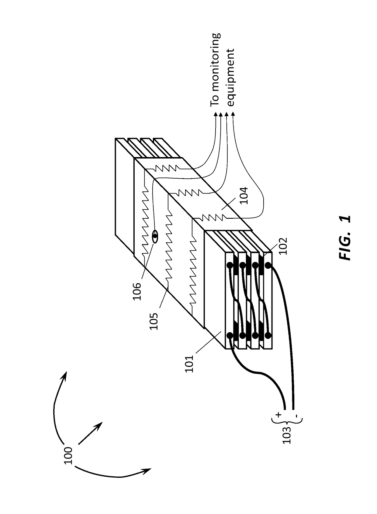
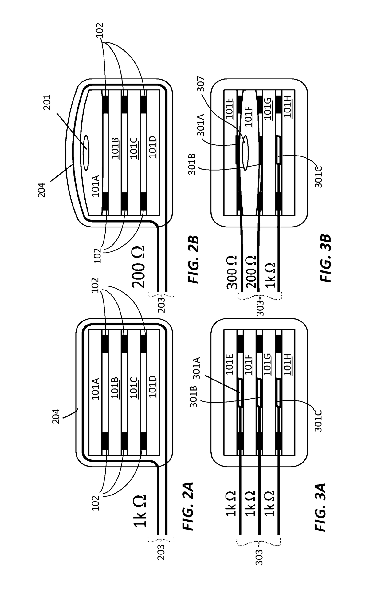
The present invention extends to methods, systems, devices, apparatus, and computer program products for protecting against runaway thermal failure of a battery pack. A fireproof container is built with a thermo-sensitive panel cover leading to the outside environment. When battery failure causes temperatures to rise inside one of the compartments, the panel cover material reacts, causing it open, allowing flames and hot gasses to vent and preventing the buildup of heat internally. Internal sensors may detect the activation of the cover material and allow an electric or electronic circuit to isolate the contents of the failed container from the rest of the system.

Description

CROSS-REFERENCE TO RELATED APPLICATIONS[0001]This application claims the benefit of and priority to U.S. Provisional Patent Application Ser. No. 61 / 975,378 entitled “Battery Status and Failure Detector And Battery Failure Venting System”, filed Apr. 4, 2014 by Paul E. I. Pounds, the entire contents of which are expressly incorporated by reference.BACKGROUND1. Background and Relevant Art[0002]Battery condition monitors typically use electronic means to determine battery condition. For example, a battery condition monitor can be configured to sense abnormal electrical charge status. Abnormal electrical charge status can indicate that conductive charge-storing elements inside the battery have failed. Unfortunately, prior to a battery being discharged in operation, typical battery condition monitors are unable to distinguish between an overcharged battery with internal failure and a battery that is operating normally. Requiring a battery to be in operation to identify an overcharge cond...

Claims


Application Information

Patent Timeline
IPC IPC(8): H01M2/12B64D45/00B60L50/64
CPCH01M2/1235B64D45/00H01M2220/20B64D2045/009H01M2/12H01M2/1205H01M2/1211H01M2/1229H01M2200/10H01M2200/103H01M10/625H01M10/613H01M10/658Y02E60/10H01M50/342H01M50/375H01M50/581H01M10/482H01M50/249B60L50/64H01M10/486H01M50/209Y02T10/70B64U20/96B64U50/30B64U20/60H01M50/30H01M50/308H01M50/325B64U2201/20G01R31/392G01R31/396H01M10/4285
Inventor POUNDS, PAUL E. I.
Owner EL-SIGHT LTD
Learn More