Method and apparatus for measuring solar cells

a solar cell and measurement method technology, applied in photovoltaic energy generation, photovoltaic energy generation, renewable energy products, etc., can solve the problems of overheating of the solar cell, insufficient consideration of the amount of energy introduced into the shaded solar cell, and insufficient consideration of the amount of energy introduced into the solar cell, so as to avoid unnecessary wastage, substantial differences in input energy, and safe identification

Active Publication Date: 2017-10-31
WAVELABS SOLAR METROLOGY SYST
View PDF14 Cites 1 Cited by
  • Summary
  • Abstract
  • Description
  • Claims
  • Application Information

AI Technical Summary

Benefits of technology

[0006]An advantage of the invention is that solar cells can be judged according to a predefined amount of introduced energy. They thereby become more comparable than when corresponding parameters are determined as the characteristic is measured. Different solar cells, which have substantially different energy inputs as the characteristic is measured, can thus have the same or at least similar amounts of energy input when measurements are made with a voltage or a current having a predeterminable, constant value. In the opposite case, different solar cells, which have the same or similar energy inputs as the characteristic is measured, can also have substantially different amounts of input energy when measured with a voltage or a current having a constant value. In both cases, solar cells measured with the method according to the present invention would be sorted differently from those measured according to the prior-art methods. Since the energy input into a solar cell is simulated more realistically with the present invention, only solar cells are rejected which would actually reach critical values under real operation conditions. Unnecessary wastage is thus avoided, while unsuitable solar cells are safely identified.
[0007]Advantageously, the voltage or the current is applied to the solar cell as precisely one pulse having a predeterminable, constant value for a predeterminable period of time. Measuring the solar cell thus involves particularly low time consumption.
[0008]Preferably, a maximum energy of the entire solar cell, a variance, a standard deviation, a surface area or values above the maximum energy, a posture, a position, a half-width and / or a gradient of local maxima is determined, and an energy per unit surface area is calculated from the scaled difference distribution. All values can relate to the entire surface area of the solar cell or the solar module, or to defined subareas. On the basis of these data, hot spots can be identified and evaluated.
[0009]Advantageously, a resulting maximum operating temperature of the solar cell or of a solar cell module comprising the solar cell, can be determined considering the magnitude of the local maximum, which corresponds to a maximum amount of energy deposited in the solar cell. From the maximum operating temperature, conclusions can be drawn about the properties of the solar cell in the solar cell module, or its suitability for being encased in certain materials.
[0010]In preferred embodiments, a time correlation between the measurement of the first and second distribution of radiation emitted across the solar cell surface area on the one hand and the application of the voltage or the current and the measurement of the resulting current and resulting voltage, respectively, on the other hand, is established. Preferably, the second relative distribution is measured within a constant time period after the application of the current or voltage pulse. It can thus be avoided that each solar cell to be measured is measured at a different point in time, so that direct comparison of the measurement results and thus the solar cells among each other leads to more valid results.
[0011]Optionally, the first and second relative distribution of the radiation emitted across the solar cell surface area is measured during a predeterminable period of time between 10 ms and 30 ms. This enables the quality of the measurement to be adjusted.

Problems solved by technology

Hot spots are areas on the solar cell in which an excessive current is flowing due to a local short circuit, which translates into heat so that the result may be overheating of the solar cell.
The drawback of the well-known methods is that the energy introduced into the solar cell due to measuring the characteristic varies from one solar cell to another since different solar cells heat up to differing degrees under different applied voltages or currents.
However the amount of energy introduced into a shaded solar cell is not taken into consideration when a certain voltage is applied to the solar cell.

Method used


Image

  • Method and apparatus for measuring solar cells
  • Method and apparatus for measuring solar cells
  • Method and apparatus for measuring solar cells

Examples


first embodiment

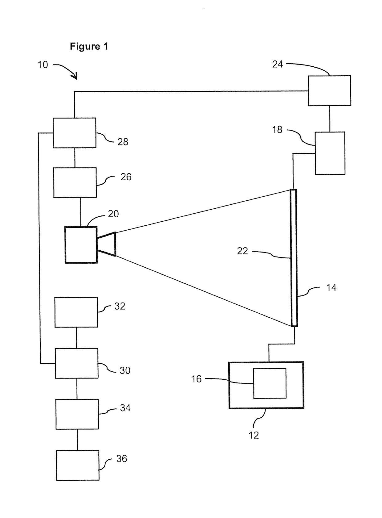
[0036]With reference to FIG. 1, an apparatus 10 for measuring solar cells is shown according to the present invention. The apparatus 10 comprises a voltage source 12 allowing a voltage U to be applied to a solar cell 14. The applied voltage U can have a value of, for example, between 0 V and −15 V. The voltage source 12 comprises a pulse generator 16 for generating and applying at least one voltage pulse to the solar cell 14. The at least one voltage pulse can be applied for a predeterminable period of time. Preferably, time periods of 1 ms to 40 ms, preferably 10 ms to 30 ms, particularly preferably 20 ms are used for one voltage pulse. Alternatively, the apparatus can also comprise a current source with a pulse generator for generating and applying at least one current pulse to the solar cell to be measured, the optionally predeterminable period of time being on the same scale as for a voltage pulse. Furthermore, the apparatus 10 comprises a current measuring apparatus 18 for meas...

second embodiment

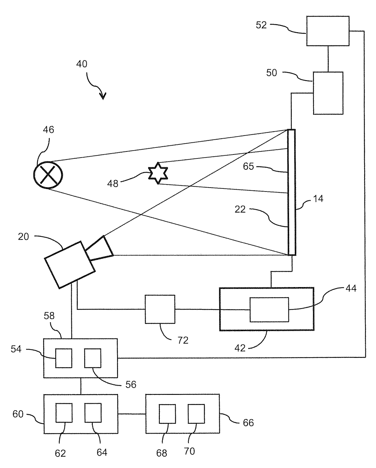
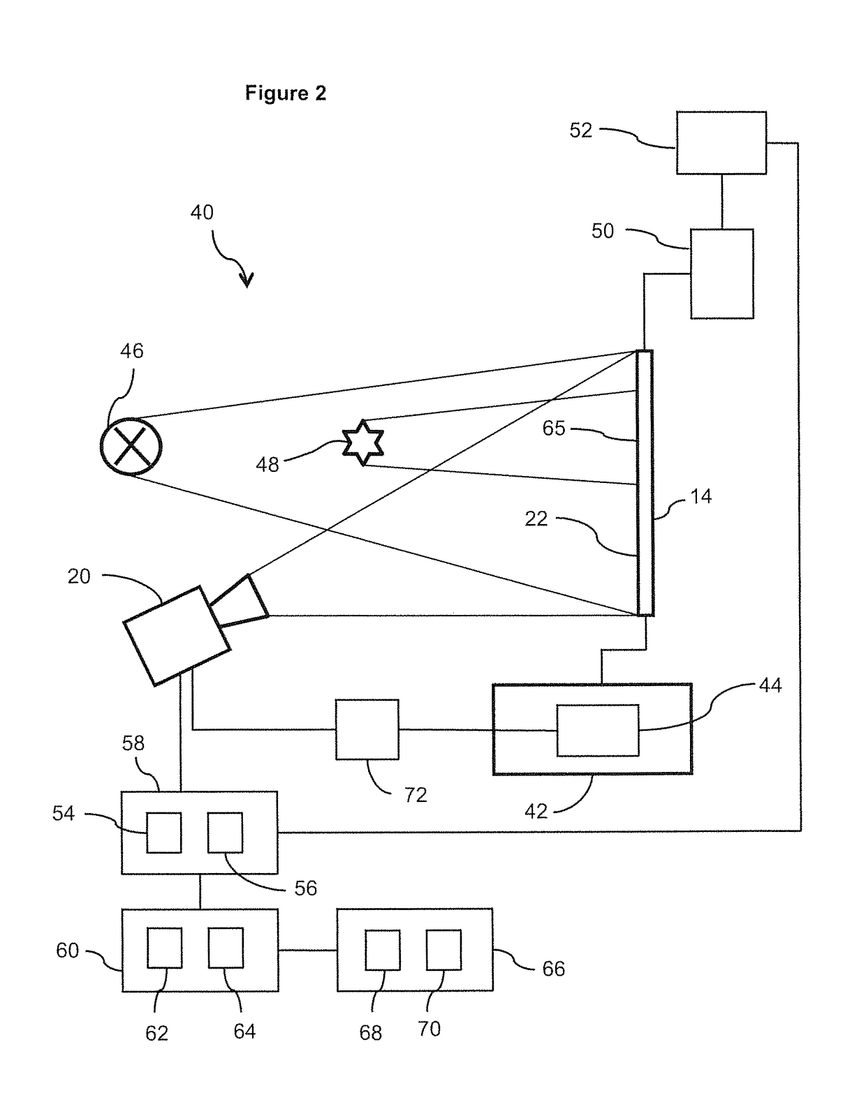
[0043]FIG. 2 shows an apparatus 40 according to the present invention. In this apparatus 40, a current source 42 and a pulse generator 44 are used to generate and apply a current pulse at 8 A, for example, which corresponds to an operating current of 35 mA / cm2 in solar cells of the usual size, to the solar cell 14. A plurality of current pulses can also be applied to the solar cell 14. Additionally, the solar cell 14 is illuminated by an illuminating means 46, wherein only part of the solar cell 14 is illuminated due to a shading apparatus 48, simply shown as a shading object in the present case. Apart from simple shading objects, such as templates, suitable shading apparatuses are, for example, controllable shading apparatuses, such as described in DE 10 2011 052 047 A1. In alternative embodiments, no shading apparatus is provided, but only an illuminating means which illuminates the solar cell 14. A voltage U resulting in the solar cell 14 from the current pulse and the shaded ill...


PUM


Abstract

A method of measuring solar cells, wherein a voltage (U) or a current (I) is applied to a solar cell, and a current (I) and voltage (U), respectively, resulting therefrom is measured, and wherein prior to applying the voltage (U) or current (I) and during or after measuring the resulting current (I) and resulting voltage (U), respectively, a relative distribution of radiation emitted across the solar cell surface area is measured, wherein the voltage (U) or current (I) is applied as at least one pulse with a predeterminable, constant value for a predeterminable period of time, wherein an energy value is calculated from the resulting current (I) and resulting voltage (U), respectively, wherein a first relative distribution of radiation emitted across the solar cell surface area is measured prior to the pulse or each pulse and a second relative distribution of radiation emitted across the solar cell surface area is measured during or after the pulse or each pulse, and wherein a difference distribution is generated from the first and second relative distributions and scaled to the calculated energy value. An apparatus for performing the method. The method and the apparatus serve for the improved sorting of solar cells.

Description

FIELD OF THE INVENTION[0001]The present invention relates to a method of measuring solar cells, wherein a voltage or a current is applied to a solar cell, and a current and voltage, respectively, resulting therefrom, are measured, and wherein prior to the application of the voltage or the current and during or after measuring the resulting current and resulting voltage, respectively, a relative distribution of radiation emitted across the solar cell surface area is measured. It also relates to a corresponding apparatus, comprising a voltage source or a current source, a current measuring apparatus and a voltage measuring apparatus, respectively, and a radiation measuring apparatus for measuring a relative distribution of radiation emitted across the solar cell surface area.BACKGROUND OF THE INVENTION[0002]Such methods and apparatus are generally known. They serve for the detection of hot spots. Hot spots are areas on the solar cell in which an excessive current is flowing due to a l...

Claims


Application Information

Patent Timeline
Patent Type & Authority Patents(United States)
IPC IPC(8): G01R31/26H02S50/10H01L31/18
CPCH02S50/10H01L31/186Y02P70/521Y02E10/50Y02P70/50
Inventor SUTHUES, JORN
Owner WAVELABS SOLAR METROLOGY SYST
Why Eureka
Try Eureka