
Turbine exhaust cylinder strut strip for shock induced oscillation control

a technology of turbine exhaust and cylinder strut, which is applied in the direction of engine fuction, fluid dynamics, machines/engines, etc., can solve the problems of affecting the stability of the tec strut, the inability to adjust the tec strut, so as to minimize the pressure fluctuations, the effect of reducing the unsteadiness of the fluid flow surrounding the tec strut and minimizing the fluctuation

Inactive Publication Date: 2017-11-07
SIEMENS ENERGY INC
View PDF11 Cites 0 Cited by
  • Summary
  • Abstract
  • Description
  • Claims
  • Application Information

AI Technical Summary

Benefits of technology

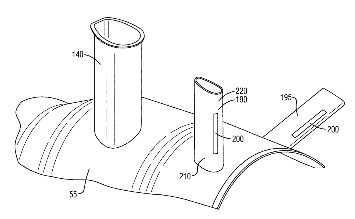
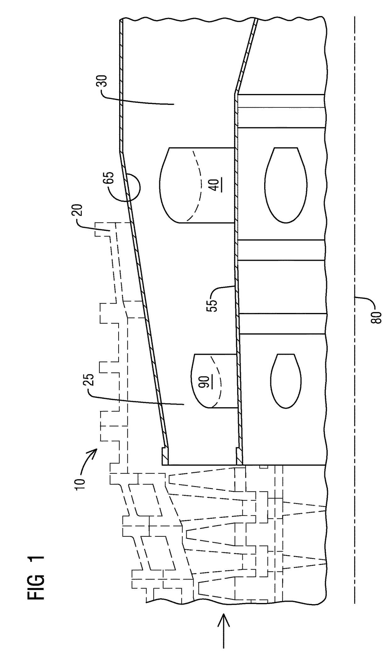
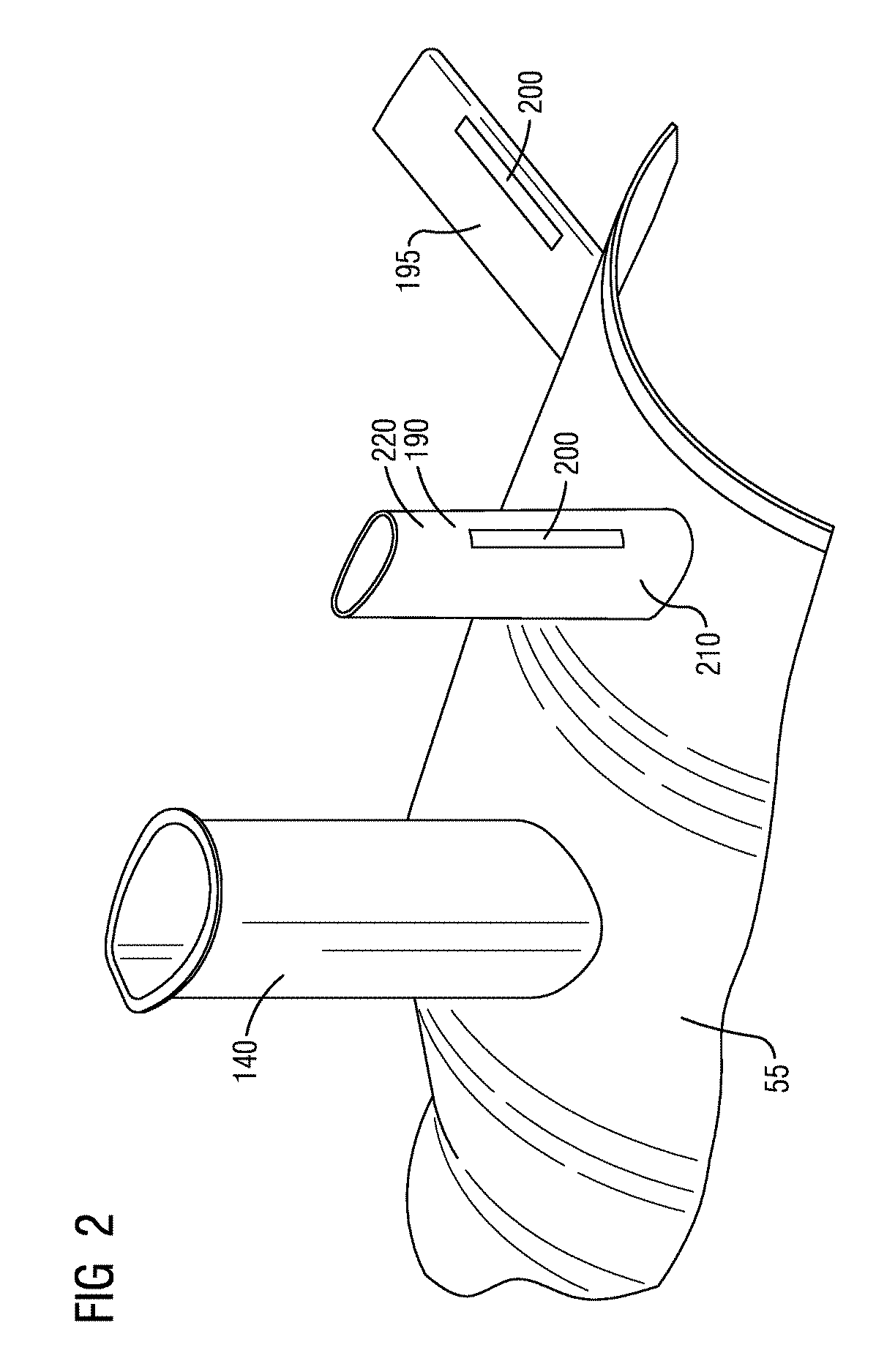
[0007]A first aspect provides an arrangement to control vibrations in a gas turbine exhaust diffuser. The arrangement includes a gas turbine exhaust diffuser. The gas turbine diffuser includes a TEM connected to a TEC establishing a fluid flow path, the fluid flow path bounded radially outward by an outer conical surface and bounded radially inward by an inner conical surface. A TEC strut is arranged in the TEC between the outer conical surface and the inner conical surface. A protrusion is disposed on the TEC strut for controlling shock induced oscillations in a gas turbine diffuser. The controlled shock induced oscillations minimize pressure fluctuations in the gas turbine exhaust diffuser such that an unsteadiness of the fluid flow surrounding the TEC strut is reduced.
[0008]A second aspect of provides a method for controlling fluid flow induced vibrations in a gas turbine diffuser. The method includes disposing a protrusion on a TEC strut of the gas turbine exhaust diffuser and coupling the protrusion to the TEC strut. The protrusion controls shock induced oscillations which minimizes pressure fluctuations in the gas turbine exhaust diffuser such that an unsteadiness of the fluid flow surrounding the TEC strut is reduced.

Problems solved by technology

At certain conditions, the exhaust flow around the struts can cause vibrations of the inner and outer diameter of the TEC and the TEM due to strut flow unsteadiness.
The strut flow unsteadiness may cause large oscillations in flowpath pressures that force the flowpath structure to vibrate or even resonate strongly.
These vibrations are a potential contributor to damage occurring on the flow path of the TEM and the TEC.
This damage to the diffuser flow path may require replacement or repair.

Method used


Image

  • Turbine exhaust cylinder strut strip for shock induced oscillation control
  • Turbine exhaust cylinder strut strip for shock induced oscillation control
  • Turbine exhaust cylinder strut strip for shock induced oscillation control

Examples


Embodiment Construction

[0013]To facilitate an understanding of embodiments, principles, and features of the present disclosure, they are explained hereinafter with reference to implementation in illustrative embodiments. Embodiments of the present disclosure, however, are not limited to use in the described systems or methods.

[0014]The components and materials described hereinafter as making up the various embodiments are intended to be illustrative and not restrictive. Many suitable components and materials that would perform the same or a similar function as the materials described herein are intended to be embraced within the scope of embodiments of the present disclosure.

[0015]While embodiments of the present disclosure have been disclosed in exemplary forms, it will be apparent to those skilled in the art that many modifications, additions, and deletions can be made therein without departing from the spirit and scope of the invention and its equivalents, as set forth in the following claims.

[0016]In ...


PUM


Abstract

An arrangement to control vibrations in a gas turbine exhaust diffuser is provided. The arrangement includes a protrusion coupled to a turbine exhaust cylinder strut for controlling shock induced oscillations in a gas turbine diffuser. The controlled shock induced oscillations minimize pressure fluctuations in the gas turbine exhaust diffuser such that an unsteadiness of the fluid flow surrounding the turbine exhaust cylinder strut is reduced. A method to fluid flow induced vibrations in a gas turbine diffuser is also provided.

Description

BACKGROUND[0001]1. Field[0002]The present application relates to gas turbines, and more particularly to an arrangement and method to minimize flow induced vibration in a gas turbine exhaust diffuser.[0003]2. Description of the Related Art[0004]The turbine exhaust cylinder and the turbine exhaust manifold are coaxial gas turbine casing components connected together establishing a fluid flow path for the gas turbine exhaust diffuser. The fluid flow path includes an inner flow path and an outer flow path defined by an inner diameter delimiting an outer conical surface of the inner flow path and an outer diameter delimiting an inner conical surface of the outer flow path, respectively. Tangential and / or radial struts, which include the corresponding strut shields that are the aerodynamic surfaces around the tangential and / or radial struts, are arranged within the fluid flow path and serve several purposes such as supporting the flow path and provide a pathway for lubrication piping. Tur...

Claims


Application Information

Patent Timeline
Patent Type & Authority Patents(United States)
IPC IPC(8): F01D25/04F15D1/00F01D25/16F01D25/30
CPCF01D25/30F01D25/04F15D1/0025F01D25/162F05D2260/964F05D2240/121
Inventor AKTURK, ALIRODRIGUEZ, JOSE L.WASDELL, DAVID L.OROSA, JOHN A.MONTGOMERY, MATTHEW D.
Owner SIEMENS ENERGY INC
Learn More