Pressure boosting device

a technology of boosting device and pressure, which is applied in the direction of machine/engine, service pipe system, and positive displacement liquid engine, etc., can solve the problems of large pressure fluctuation, time duration between switching on and off the boosting pump, and manual adaptation

Active Publication Date: 2022-05-10
GRUNDFOS MANAGEMENT AS
View PDF10 Cites 0 Cited by
  • Summary
  • Abstract
  • Description
  • Claims
  • Application Information

AI Technical Summary

Benefits of technology

[0005]With regard to this problem, it is an object of the invention, to improve a pressure boosting device for increasing the pressure of a fluid flowing through a conduit, to the extent that an automatic adaptation to the respective hydraulic system is effected for minimizing the occurring pressure fluctuations. This object is achieved by a pressure boosting device with the features according to the invention.
[0008]According to the invention, the control device is configured in a manner such that it automatically adapts at least one pressure control parameter of the control device in this start-stop operation. Such a pressure control parameter is a parameter which forms the basis of the control of the booster pump by the control device, in particular a parameter which has an influence on the points in time of switching on and switching off in start-stop operation. The automatic adaptation of this at least one pressure control parameter, according to the invention is effected on the basis of the temporal course of at least one pressure value detected by the pressure sensor. A self-learning system is thus created, which automatically adapts to the current conditions in the hydraulic system at the exit side of the pressure boosting device. Preferably the control device is configured in a manner such that the adaptation is effected in a manner such that the pressure difference between the upper and the lower limit value is minimized, without increasing the number of switch-on procedures beyond a predefined limit value. It is therefore ensured that the running time of the booster pump in the start-stop operation is essentially not extended, but at the same time the comfort is however improved by way of pressure fluctuations in the system being minimized. Thus the comfort can be increased with a simultaneous energy efficiency.
[0009]According to a preferred embodiment of the invention, the pressure boosting device or its control device is configured in a manner such that the at least one pressure control parameter which is automatically adapted, is the upper and / or the lower pressure limit value. In particular the pressure control parameter can be the difference between the upper and the lower pressure limit value, i.e. can be a hysteresis range. The adaption of the pressure limit value or their difference permits an automatically adaptation of the pressure boosting device to the connecting hydraulic system or to the conditions prevailing in the system, by way of the pressure limit values being adapted such that the pressure difference is minimized in operation, without significantly increasing the number of switch-on procedures or the total switch-on duration of the booster pump. A gain in comfort is therefore achieved. In particular, an adaptation of the system to a tank volume of a buffer tank in the system is possible. It is possible to reduce the pressure difference with larger volumes, so that as a whole reduced pressure fluctuations occur in the system.
[0012]According to a further preferred embodiment, the control device is configured such that it puts the mentioned evaluation time periods into time periods, in which a speed of a booster pump is increased or reduced by the control device. This has the advantage that the dependency of the change of the measured pressure in the system on the speed change can be considered. One can assess as to whether the pressure follows the speed change in the expected manner, which is to say the change of the actually detected pressure follows a defined or intended pressure change.
[0017]The prediction system is preferably designed such that it applies a prediction model which is an autoregressive model (ARX model), in particular an autoregressive model (ARX model) of the first order. A prediction of the pressure values can be achieved in a simple manner on the basis of such a model. At least one applied system-parameter can moreover be adapted in the manner described above in such a model, in order to minimize the prediction error.
[0018]According to a further preferred embodiment, the control device is configured in a manner such that the at least one pressure control parameter is set in dependence on the at least one system-parameter in the prediction model, in particular on the basis of a predefined algorithm or a table, in particular a predefined table which is stored in the control device. Thus in particular, the pressure limit values which are described above, as pressure control parameters, can be likewise adapted in dependence on the system-parameter in the prediction model, said parameter being adapted in the manner described above. Thus the pressure control parameter which in the start-stop operation preferably has an influence on the switch-on and / or switch-off points in time of the booster pump, is adapted in dependence on the at least one adapted system parameter, so that apart from the minimisation of the prediction error in the previously described manner, the pressure difference between switching on and switching off the booster pump can be minimized and thus a gain in comfort can be achieved.

Problems solved by technology

If such a pressure boosting device is operated in the mentioned start-stop operation, then there exist the problem of the time duration between switching the booster pumps on and off, amongst other things being dependent on how large the volume in the connecting conduit system is and in particular in a buffer tank which is present as the case may be.
A large volume leads to large pressure fluctuations over a comparatively long time period.
In previous systems, this can only be achieved by manual adaptation.

Method used


Image

  • Pressure boosting device
  • Pressure boosting device
  • Pressure boosting device

Examples


Embodiment Construction

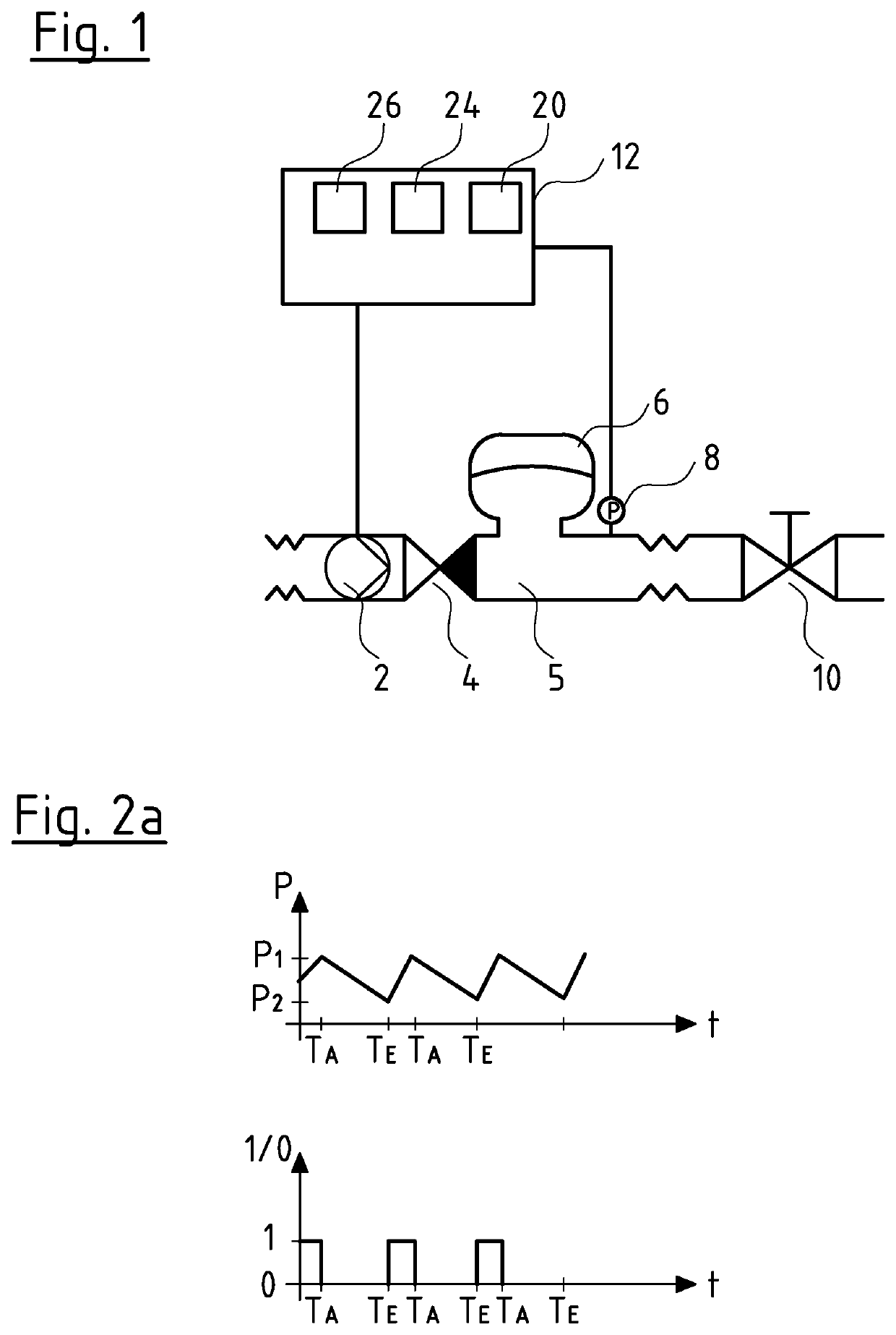
[0035]Referring to the drawings, FIG. 1 schematically shows a pressure boosting device in a drinking water supply conduit. The pressure boosting device comprises a booster pump 2, to which a non-return valve 4 connects further downstream at the exit side. A buffer tank 6 is arranged at the exit side of the non-return valve 4 and in the usual manner can be designed as a storage tank with a membrane and a closed air volume which is arranged thereabove. A pressure sensor 8 which detect the pressure P at the exit side of the booster pump 2 and at the exit side of the non-return valve 4 is arranged further downstream. A valve 10 is represented schematically further downstream and is to represent one or more consumers, for example tapping locations and via which the flow in the conduit 5 is set at the exit side of the non-return valve 4. It is to be understood that in practice, a branched network / mains with a multitude of valves 10 can connect to the conduit 5 instead of one valve 10.

[003...


PUM


Abstract

A pressure boosting device increases pressure of a fluid flowing through a conduit (5) and includes a booster pump (2), a control device (12), controlling the booster pump (2), as well as a pressure sensor (8) arranged at the exit side of the booster pump (2) and connected to the control device. The control device (12) is configured to control the booster pump, in an operating region, in a start-stop operation, a switching off of the booster pump (2) when reaching an upper pressure limit value (P1) and a switching on of the booster pump (2) when reaching a lower pressure limit value (P2). The control device (12) is further configured in a start-stop operation to automatically adapt at least one pressure control parameter (P1, P2) of the control device (12) on the basis of the temporal course of at least one pressure value (P) detected by the pressure sensor.

Description

CROSS REFERENCE TO RELATED APPLICATIONS[0001]This application claims the benefit of priority under 35 U.S.C. § 119 of European Application 15 190 110.5 filed Oct. 16, 2015, the entire contents of which are incorporated herein by reference.FIELD OF THE INVENTION[0002]The invention relates to a pressure boosting device for increasing the pressure of a fluid flowing through a conduit.BACKGROUND OF THE INVENTION[0003]Such pressure boosting devices are applied for example in the drinking water supply of buildings, if the conduit-side pressure which prevails in a drinking water supply is not adequately high, in order to deliver the drinking water to the uppermost floors of a building. Such pressure boosting devices comprise one or more booster pumps which can be connected in parallel or in series and which are switched on when the pressure at the exit side of the booster pumps falls short of a predefined limit value. Accordingly, the booster pumps are switched off again after reaching a d...

Claims


Application Information

Patent Timeline
Patent Type & Authority Patents(United States)
IPC IPC(8): E03B5/02F04D27/00F04B49/02F04B49/06
CPCF04B49/02E03B5/02F04B49/06F04B49/065F04D27/008F04B2205/04F04B2205/05F04B2205/06E03B7/09E03B7/04F04D15/0027F04D15/0066
Inventor DISSING, TORBEN THORSAGER
Owner GRUNDFOS MANAGEMENT AS
Why Eureka
Try Eureka