Plasma processing method

a processing method and technology of plasma, applied in the field of plasma processing method, can solve the problems of abnormal process dimension, short circuit of semiconductor wiring, and no consideration of particle attachment, etc., to achieve the effect of reducing the pressure fluctuation within the processing chamber, reducing the amount of particles attached to the sample, and reducing the amount of particles attached

Active Publication Date: 2009-08-27
HITACHI HIGH-TECH CORP
View PDF5 Cites 0 Cited by
  • Summary
  • Abstract
  • Description
  • Claims
  • Application Information

AI Technical Summary

Benefits of technology

[0009]The object of the present invention is to provide a plasma processing apparatus and a plasma processing method capable of minimizing pressure fluctuation in the processing chamber during a series of processes from the carrying in of the sample to the processing chamber, plasma processing of the sample and carrying out of the sample, and thereby reducing the attaching of particles to the sample.
[0011]According to the above-described method, plasma is generated from transferring gas, and the plasma is maintained while continuously switching supplied gas from transferring gas to processing gas, and after the plasma processing is terminated, the plasma is maintained while continuously switching supplied gas from processing gas to transferring gas, so that the sample is carried out while the supply of transferring gas is continued, and the pressure fluctuation within the processing chamber is minimized, according to which the attaching of particles to the sample due to flinging up of particles by airflow is reduced, and the attaching of particles is further reduced by evacuating the particles existing in the plasma at the time the plasma processing is terminated by the airflow of transferring gas.

Problems solved by technology

In a conventional plasma processing apparatus that utilizes chemical reaction between processing gases and samples such as semiconductor wafers to process the samples, there are drawbacks in that reaction products, which are deposited on inner side walls of the processing chambers when processes generating reaction products are performed continuously, are detached from the walls and are attached to the samples, and in that the atmosphere containing residual components residing in the processing chamber affects the surface of the samples, causing defects such as short circuit of the semiconductor wiring and abnormal process dimension.
However, there has not been any consideration on the flinging up of particles caused by pressure fluctuation within the processing chamber during the continuous processing from when the sample is carried into the processing chamber to when the sample having been subjected to plasma processing is carried out of the processing chamber.
However, the above document does not disclose how a sample is carried into the processing chamber from the transfer chamber while supplying transferring gas into the processing chamber, how plasma is generated from transferring gas, how transferring gas is switched to processing gas while maintaining plasma to perform plasma processing, how processing gas is switched to transferring gas while maintaining plasma by processing gas, and how plasma is terminated and then the sample is carried out of the processing chamber to the transfer chamber.

Method used


Image

  • Plasma processing method
  • Plasma processing method
  • Plasma processing method

Examples


Embodiment Construction

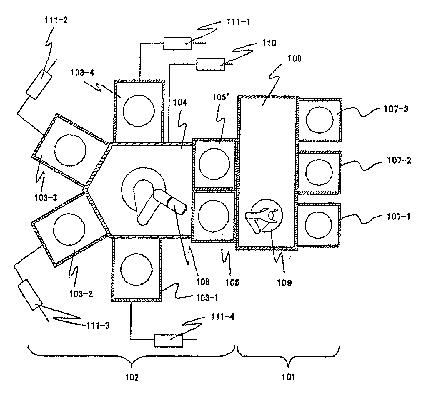
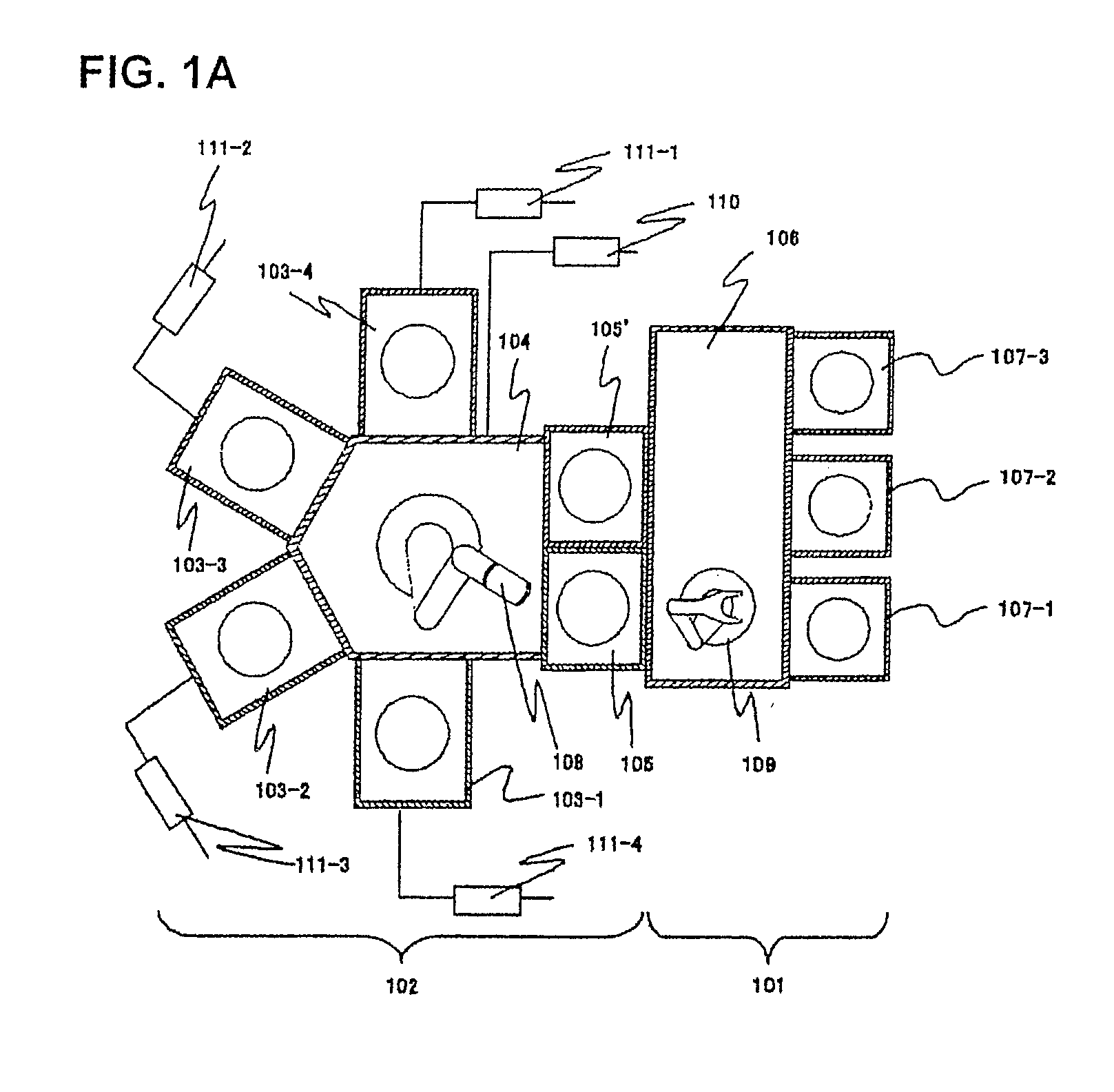
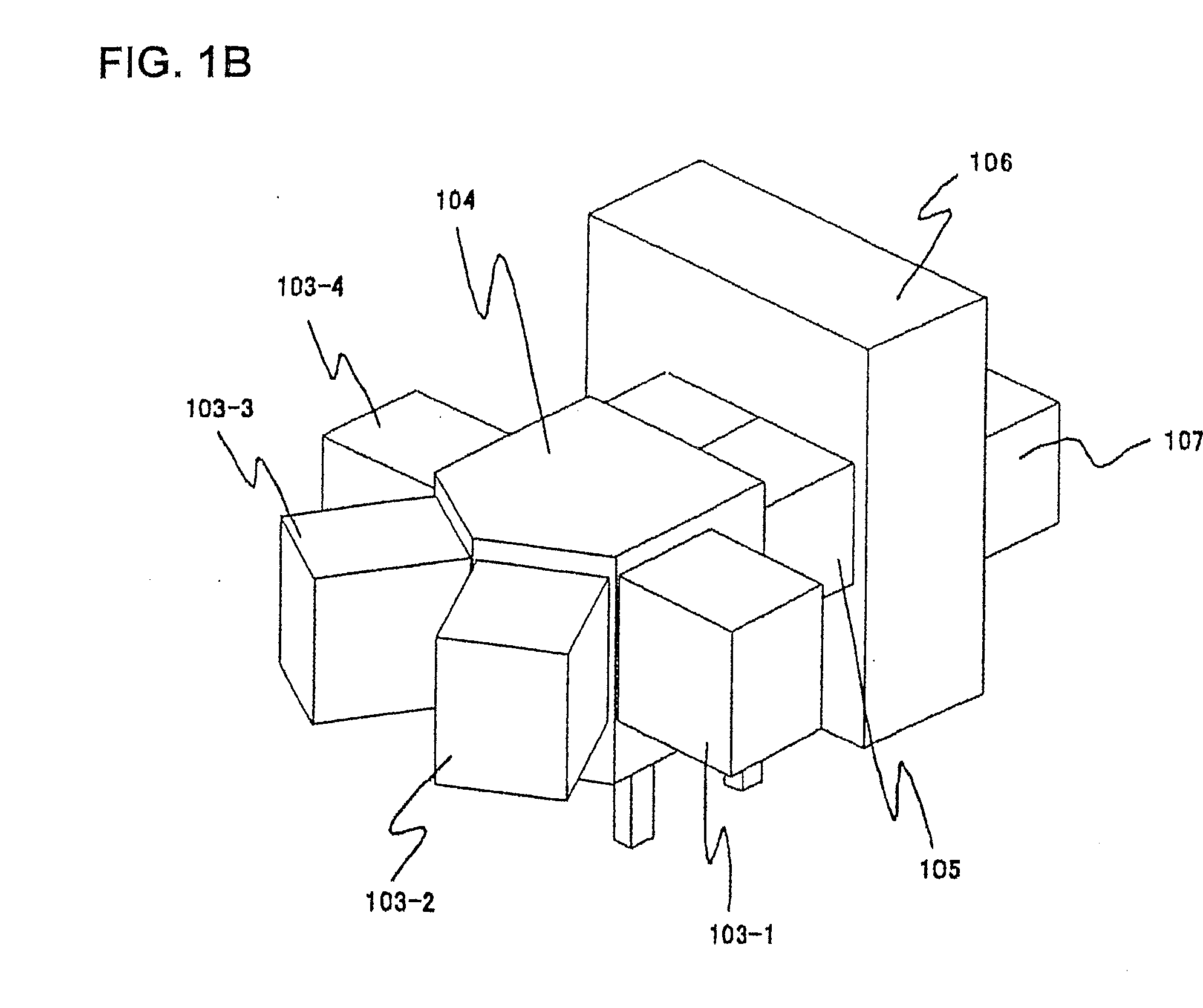
[0017]With reference to FIG. 1, the overall structure of a plasma processing apparatus for carrying out the present invention will be described. FIG. 1A is an upper cross-sectional view of the plasma processing apparatus, and FIG. 1B is a perspective side view thereof. The plasma processing apparatus is largely divided into an atmospheric block 101 and a processing block 102. The atmospheric block 101 is the portion in which wafers are transferred in atmospheric pressure to be stored or positioned, and the processing block 102 is the portion in which wafers are transferred under pressure depressurized from atmospheric pressure for processing, and the pressure thereof is varied while the wafer is placed therein.

[0018]The atmospheric block 101 has a housing 106 with a transfer robot 109 disposed therein, and includes cassettes 107-1 through 107-3 attached to the housing having processing samples or cleaning samples stored therein.

[0019]The processing block 102 has processing chambers ...


PUM

PropertyMeasurementUnit
plasmaaaaaaaaaaa
gas flow rateaaaaaaaaaa
pressureaaaaaaaaaa

Abstract

The invention provides a plasma processing method capable of reducing particle caused by flinging up of particles by airflow due to the pressure fluctuation in the processing chamber during the time the sample is carried into the processing chamber, subjected to plasma processing and carried out of the processing chamber. The invention provides a plasma processing method using a plasma processing apparatus comprising multiple plasma processing chambers for processing samples, a transfer chamber connected to the processing chambers for transferring samples, and a supply system for supplying gas which is the same gas as a transferring gas supplied to the transfer chamber to both the processing chambers and transfer chamber or to only the processing chambers, wherein the process comprises (b) a step of transferring the sample into the processing chamber with the transferring gas supplied to the processing chamber; (c) thereafter, generating plasma from the transferring gas supplied to the processing chamber while maintaining the supply of transferring gas to the processing chamber; (d) a step of switching the gas supplied to the processing chamber from transferring gas to processing gas while maintaining plasma by supplying processing gas continuously to the processing chamber; and (e) a step of subjecting the sample to plasma processing.

Description

[0001]The present application is based on and claims priority of Japanese patent application No. 2007-58664 filed on Mar. 8, 2007, the entire contents of which are hereby incorporated by reference. This application is a Continuation application of application Ser. No. 11 / 834,046, filed Aug. 6, 2007, the contents of which are incorporated herein by reference in their entirety.BACKGROUND OF THE INVENTION[0002]1. Field of the Invention[0003]The present invention relates to a plasma processing method using a plasma processing apparatus comprising a plurality of plasma processing chambers for processing samples such as semiconductor wafers, a transfer chamber connected to the processing chambers for transferring samples and a supply system for supplying gas which is the same gas as the transferring gas supplied to the transfer chamber to both the transfer chamber and processing chambers or only to the processing chambers when transferring samples from the transfer chamber to the processi...

Claims


Application Information

Patent Timeline
Patent Type & Authority Applications(United States)
IPC IPC(8): B01J19/08
CPCH01J37/3244H01J37/32743H01L21/67213H01L21/67069H01J37/32788
Inventor ISHIHARA, MASUNORISAKAGUCHI, MASAMICHINISHIMORI, YASUHIROKUDOU, YUTAKAUNE, SATOSHI
Owner HITACHI HIGH-TECH CORP
Why Eureka
Try Eureka