
Apparatus for turbulent boundary layer control and flow noise reduction

a technology of boundary layer control and apparatus, applied in the field of apparatus for turbulent boundary layer control and flow noise reduction, can solve the problems of flow noise, reducing the effectiveness of sonar, and hull-mounted and towed arrays subject to flow noise, so as to reduce drag, minimize turbulent wall pressure fluctuations, and improve sonar performance

Inactive Publication Date: 2014-07-08
UNITED STATE OF AMERICA THE
View PDF1 Cites 1 Cited by
  • Summary
  • Abstract
  • Description
  • Claims
  • Application Information

AI Technical Summary

Benefits of technology

This patent presents an assembly and method for improving sonar performance over a range of speeds while reducing drag. The assembly includes a water tunnel, a large eddy breakup device (LEBU), and a wall pressure sensor array. The method involves changing the design of the LEBU and affecting the distribution of energy in the wall pressure fluctuations to minimize turbulent wall pressure fluctuations. This design helps to reduce flow noise and vibrations, resulting in better sonar performance.

Problems solved by technology

Currently, hull-mounted and towed arrays are subject to flow noise due to turbulent wall pressure fluctuations on the arrays.
Flow noise can mask an acoustic signal with the result of reducing the effectiveness of the sonar.
A primary source of flow noise is the turbulent wall pressure fluctuations on hull mounted and towed arrays at most operational speeds due to high Reynolds numbers involved.
To date, this level of control has not been widely achieved.
The implementation of turbulence control technology is closely related to the complexity and cost of execution.
While this technique may work for flow noise reduction, implementation of polymer injection involves a major impact to the hull and the environment.
However, the cost, complexity and ship impact of implementation is excessive in comparison to the use of a LEBU.

Method used


Image

  • Apparatus for turbulent boundary layer control and flow noise reduction
  • Apparatus for turbulent boundary layer control and flow noise reduction
  • Apparatus for turbulent boundary layer control and flow noise reduction

Examples


Embodiment Construction

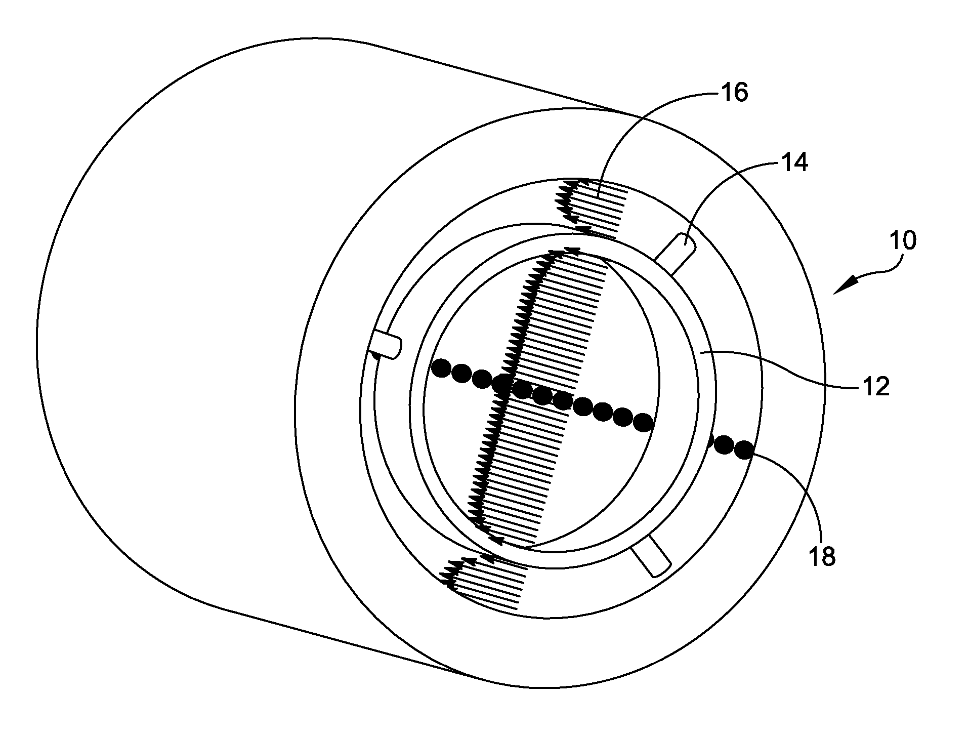
[0022]Referring now to the drawings, and more particularly to

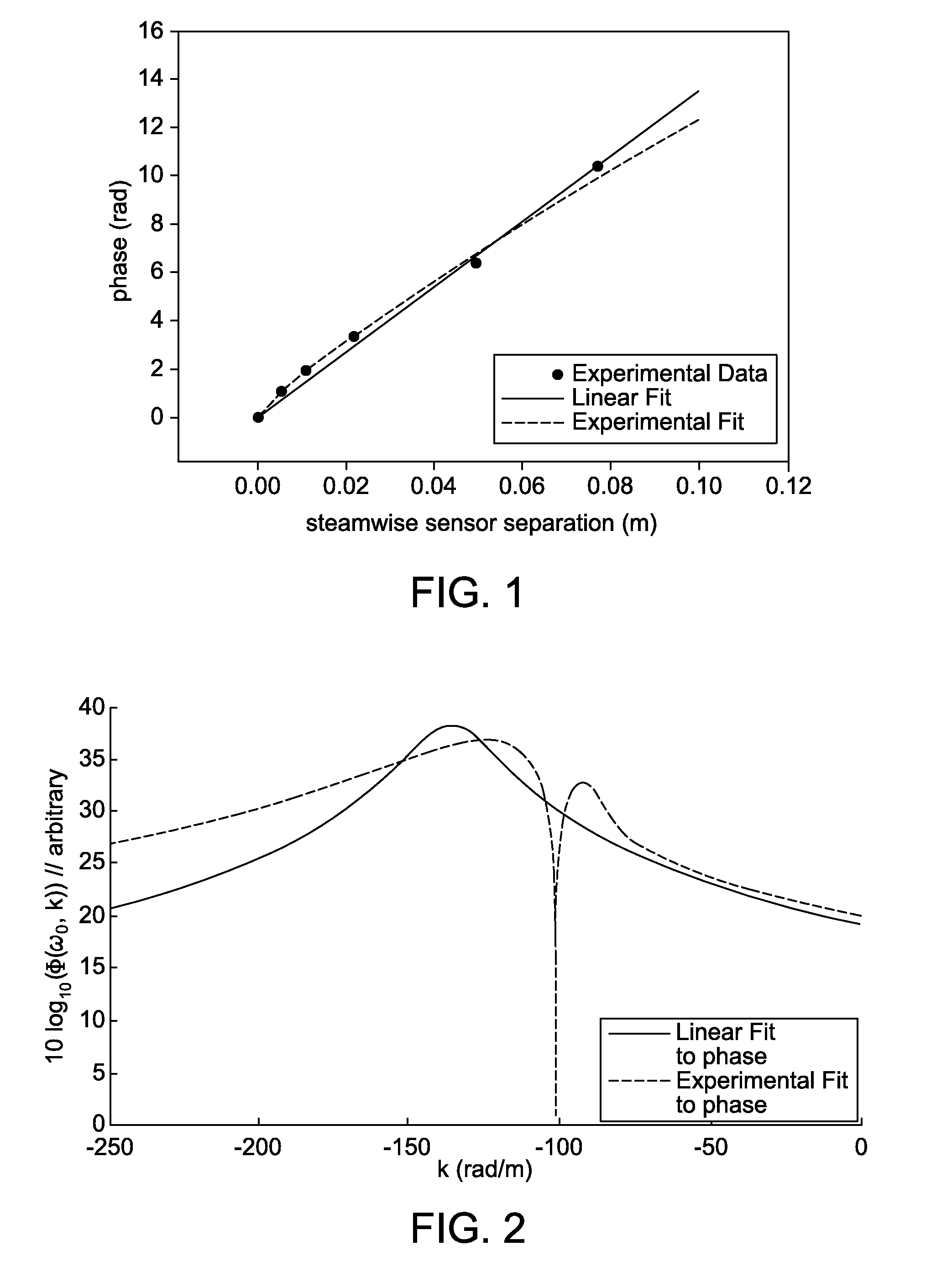
[0023]FIG. 1 and FIG. 2, for a particular frequency ω0, the wavenumber-frequency spectrum Φ(ω0, k), is related to the cross-spectrum, G(ω0, ξ), by

Φ(ω0,k)=1 / 2π∫−∞∞G(ω0,ξ)e−ikξdξ.  (1)

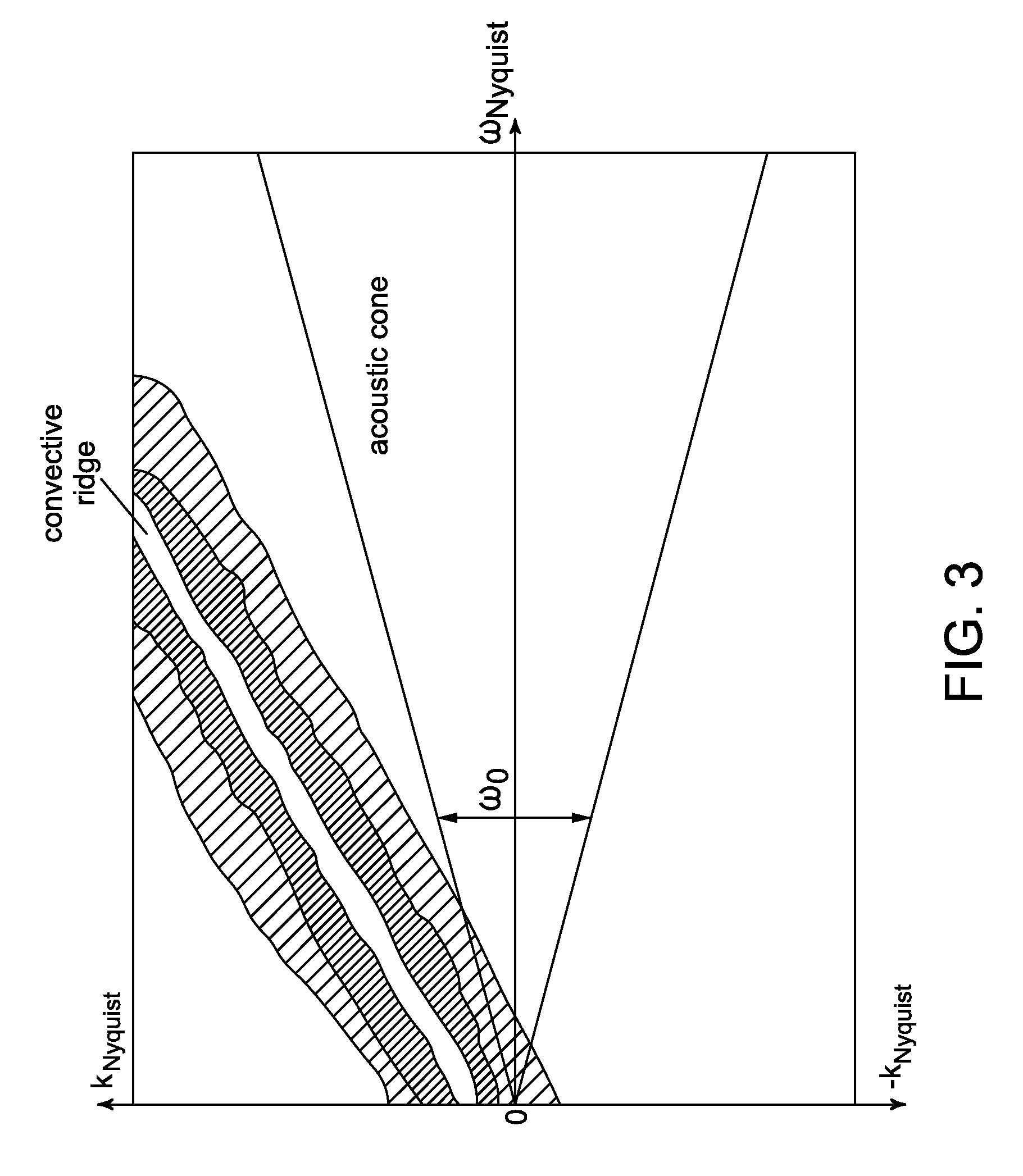
[0024]To estimate Φ(ω0, k) from Equation (1), the magnitude and phase of G(ω0, ξ) must be established. Curve fits were made to the magnitude and phase of cross spectral data taken during a towed array tow tank test. Subtle changes in the curve fits to the phase (FIG. 1) resulted in substantial changes to the computed wavenumber spectrum (FIG. 2) at a fixed frequency ω0 at which the turbulent energy was dominated by direct turbulent boundary layer wall pressure fluctuations. From the same data set, the direct measurement of wavenumber frequency spectra showed variations in spectral levels in low wavenumbers. These variations could result from the phase shift mechanism. There is uncertainty as to whether these dropouts or nulls are artifacts of t...


PUM


Abstract

An assembly is provided for determining a parametric design of a large eddy breakup device in which the assembly comprises a water tunnel turbulent pipe flow section; a large eddy breakup device ring disposed within the pipe flow section; and a wall pressure sensor array operable to detect wall pressure in the turbulent pipe flow section. Energy in a wavenumber frequency spectra of wall pressure fluctuations is redistributed via changes to the parametric design in order to minimize turbulent wall pressure fluctuations with the result of reduced flow noise and drag.

Description

STATEMENT OF GOVERNMENT INTEREST[0001]The invention described herein may be manufactured and used by or for the Government of the United States of America for governmental purposes without the payment of any royalties thereon or therefor.CROSS REFERENCE TO OTHER PATENT APPLICATIONS[0002]None.BACKGROUND OF THE INVENTION[0003](1) Field of the Invention[0004]The present invention relates to sonar noise reduction. More particularly, the present invention relates to an apparatus and method of use for the passive control of flow noise from flow-induced vibration of sonar systems.[0005](2) Description of the Prior Art[0006]Currently, hull-mounted and towed arrays are subject to flow noise due to turbulent wall pressure fluctuations on the arrays. Flow noise can mask an acoustic signal with the result of reducing the effectiveness of the sonar.[0007]A primary source of flow noise is the turbulent wall pressure fluctuations on hull mounted and towed arrays at most operational speeds due to h...

Claims


Application Information

Patent Timeline
Patent Type & Authority Patents(United States)
IPC IPC(8): G01S15/02
CPCG01S7/521G01S15/02
Inventor KEITH, WILLIAM LFOLEY, ALIA W
Owner UNITED STATE OF AMERICA THE
Learn More