
Airway Pressure Release Ventilator

a ventilator and airway technology, applied in the field of ventilators, can solve the problems of high energy consumption, high maintenance cost, and unpredictable failure rate tim

Pending Publication Date: 2021-10-21
ORICS IND INC
View PDF0 Cites 0 Cited by
  • Summary
  • Abstract
  • Description
  • Claims
  • Application Information

AI Technical Summary

Benefits of technology

The present invention is a ventilation system that uses a non-motorized system to push air into a patient's lungs. It includes a monitor to ensure a constant and uniform purge of oxygen and air, and a control mechanism to regulate the pressure during at least one exhalation cycle to allow for carbon dioxide release. The method is designed to provide a constant and uniform purge of oxygen and air while minimizing supply pressure fluctuation.

Problems solved by technology

Electro-mechanical systems like motors and pumps have a predictable fail rate time, require maintenance, consume high amounts of energy, generate heat waste and add bulk to a ventilator design.

Method used


Image

  • Airway Pressure Release Ventilator
  • Airway Pressure Release Ventilator
  • Airway Pressure Release Ventilator

Examples


first embodiment

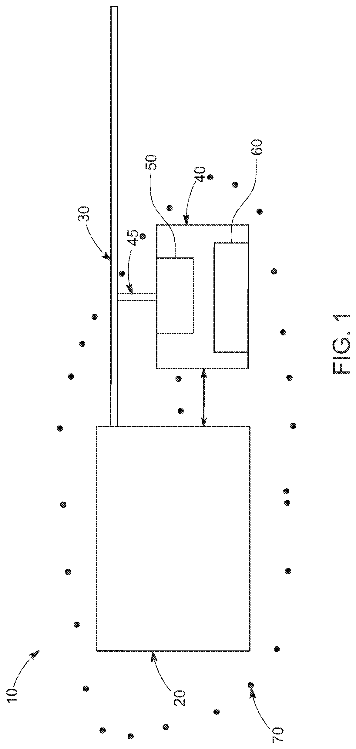
[0040]Referring to FIG. 1, the present disclosure is illustrated. Here, a system 10 is depicted for ventilating patients in needs of supplemental respiration support. System 10 includes a medical sealed apparatus 20 for storing pressurized gases. Apparatus 20 can be realized by various means apparent to skilled artisans upon reading the teachings of disclosure herein. In one embodiment, apparatus 20 is a gas holding reservoir tank. In this regard, apparatus 20 is a storage unit for pressurized gases. In one embodiment, these pressurized gases include oxygen (O2) and air. It should be apparent to skilled artisans upon reading the disclosure herein that other gases may be included for other applications including, for example, anesthesia.

[0041]Ventilating system 10 further includes breathing tube 30. Breathing tube 30 is mechanically coupled to gas holding reservoir tank 20. Breathing tube 30 ultimately delivers the pressurized gas to the patient in need of supplemental respiration su...

second embodiment

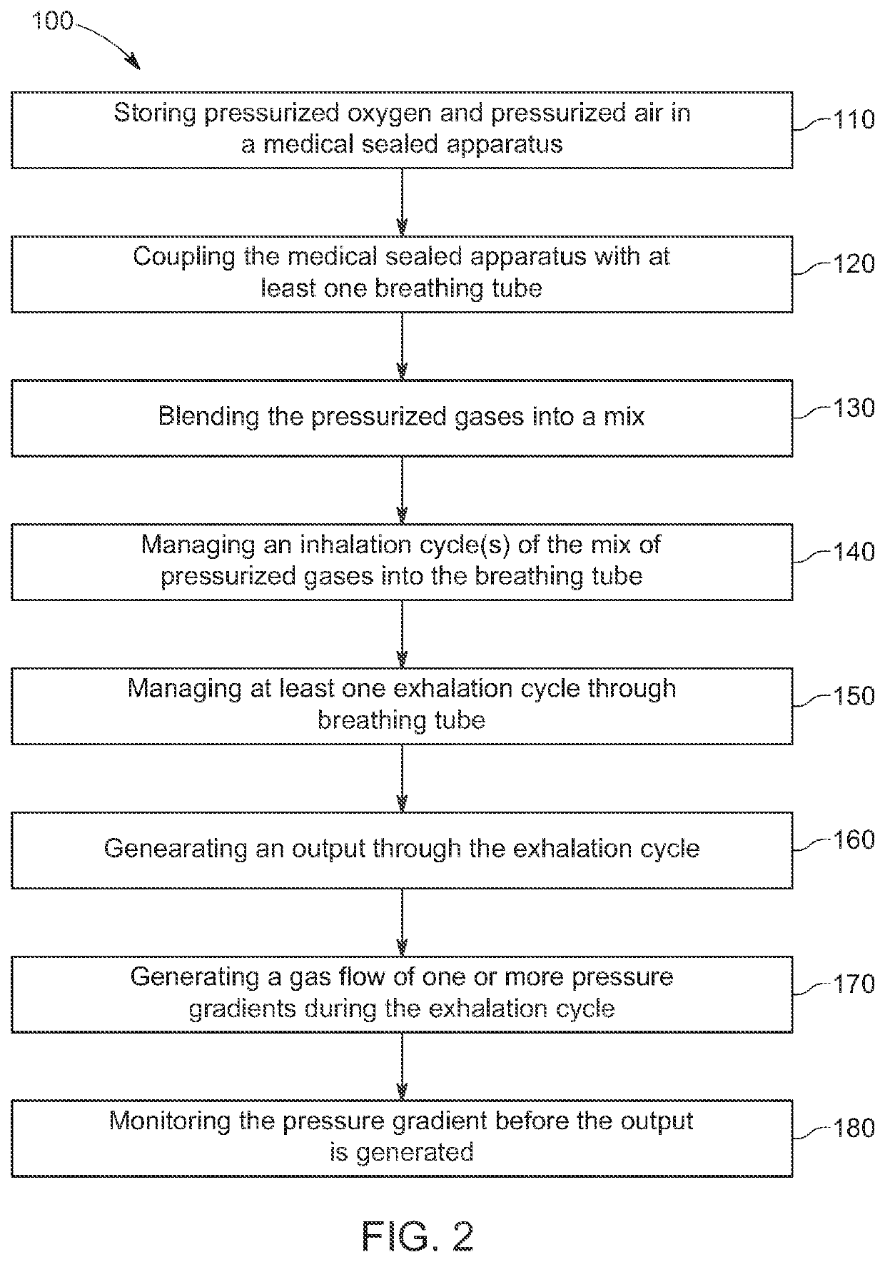
[0051]Referring to FIG. 2, the present disclosure is illustrated. Here, a flow chart is depicted for a method 100 for ventilating medical patients. Method 100 of this embodiment begins with the step 110 of storing one or more pressurized gases in a medically sealed apparatus or, a gas holding reservoir tank. The pressurized gases stored in this step will include oxygen (O2) and air. It should be apparent to skilled artisans upon reading the disclosure herein that other gases may be included for other applications including, for example, anesthesia.

[0052]Once the pressurized gases are stored in a medically sealed apparatus of step 110, the apparatus is then coupled 120 with one or more breathing tubes. This coupling, ultimately, is allow a specific mix of pressurized gas to flow through the breathing tube and enable the patient to ventilate their pulmonary system.

[0053]After the medically sealed apparatus is coupled with the breathing tube, method 100 then calls for blending 130 the ...


PUM


Abstract

A system and method for ventilating includes a holding tank, such as, for example, a medical sealed apparatus, for storing of gases. The holding tank stores at least pressured oxygen, for example O2, though the holding tank may store a pressurized blend of oxygen and air. This blend may include a 50-50 mix of oxygen and air. The pressure applied to the gases in the holding tank may include a range from 5 pounds force per square inch to 20 pounds force per square inch. The blend of oxygen and air, for example, under pressure in the holding tank, the system and method for ventilating of the present disclosure no longer requires an electronic mechanical system, such as, for example, a pump or motor on the inhalation control and the exhalation control to the ventilating system and method.

Description

BACKGROUNDField of the Disclosure[0001]The present disclosure generally relates to medical equipment generally, and more particularly, to a ventilator.Description of Related Art[0002]This section intends to provide a background discussion for a clear understanding of the disclosure herein but makes no claim nor any implication as to what is the relevant art for this disclosure.[0003]Various medical equipment are currently employed in supporting impaired human breathing, most commonly referred to a ventilators. A ventilator may be defined as a device machine that provides mechanical ventilation by moving breathable air into and out of the lungs, thereby delivering breaths to a patient who is impaired or physically unable to breathe or breath sufficiently. While numerous ventilator designs exist, the most advanced systems rely on computer controlled systems though a simple, hand-operated bag valve mask design are still in use.[0004]With the recent rise of The Coronavirus or Covid 19, ...

Claims


Application Information

Patent Timeline
IPC IPC(8): A61M16/00A61M16/12
CPCA61M16/024A61M16/12A61M2202/0208A61M2016/003A61M2016/0027A61M16/1005A61M16/125A61M2205/3331A61M2205/3334A61M2205/3341A61M16/0051A61M16/0858A61M2016/0036A61M16/202A61M16/208A61M16/107A61M16/209A61M16/204A61M16/04A61M16/0057A61M16/122
Inventor COHEN, ORICOHENMILLA, CARLOS
Owner ORICS IND INC
Learn More