
Channel allocation method and apparatus for use in a wireless communication local area network

a wireless communication and local area network technology, applied in the direction of transmission, wireless communication, network topologies, etc., can solve the problems of large workload, many difficulties in installing, debugging and maintaining the network, and bringing with them various requirements and problems

Inactive Publication Date: 2017-11-07
SIGNIFY HLDG BV
View PDF11 Cites 1 Cited by
  • Summary
  • Abstract
  • Description
  • Claims
  • Application Information

AI Technical Summary

Benefits of technology

This method simplifies the channel allocation process, reducing errors and workload, enabling efficient remote control of nodes in wireless communication networks, particularly beneficial in large-scale lighting and inductor networks.

Problems solved by technology

At the same time, however, these networks bring with them various requirements and problems.
The conventional technique is to connect a console and the plurality of nodes by cables to form a network, but this causes many difficulties in installing, debugging, and maintenance of the network.
In a wireless communication system, however, the respective nodes are mutually independent, and the console cannot automatically determine the physical locations of the respective nodes, so the correspondence between a specific channel and the physical location of a node cannot be automatically obtained, which is an inconvenience in the use of the wireless communication technique.
However, this method involves a great workload, a complicated execution process, a long execution time, and a high error rate.
Especially if the number of nodes is very large, it will become very difficult to allocate a respective channel to each node in this way.
The above problem is typical in remotely controlled lighting networks.
In fact, the same problem exists in other fields of control through wireless communication.
If there is a large number of inductors present, the above-mentioned difficulties are inevitable.

Method used


Image

  • Channel allocation method and apparatus for use in a wireless communication local area network
  • Channel allocation method and apparatus for use in a wireless communication local area network
  • Channel allocation method and apparatus for use in a wireless communication local area network

Examples


Embodiment Construction

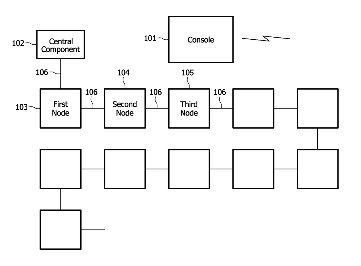
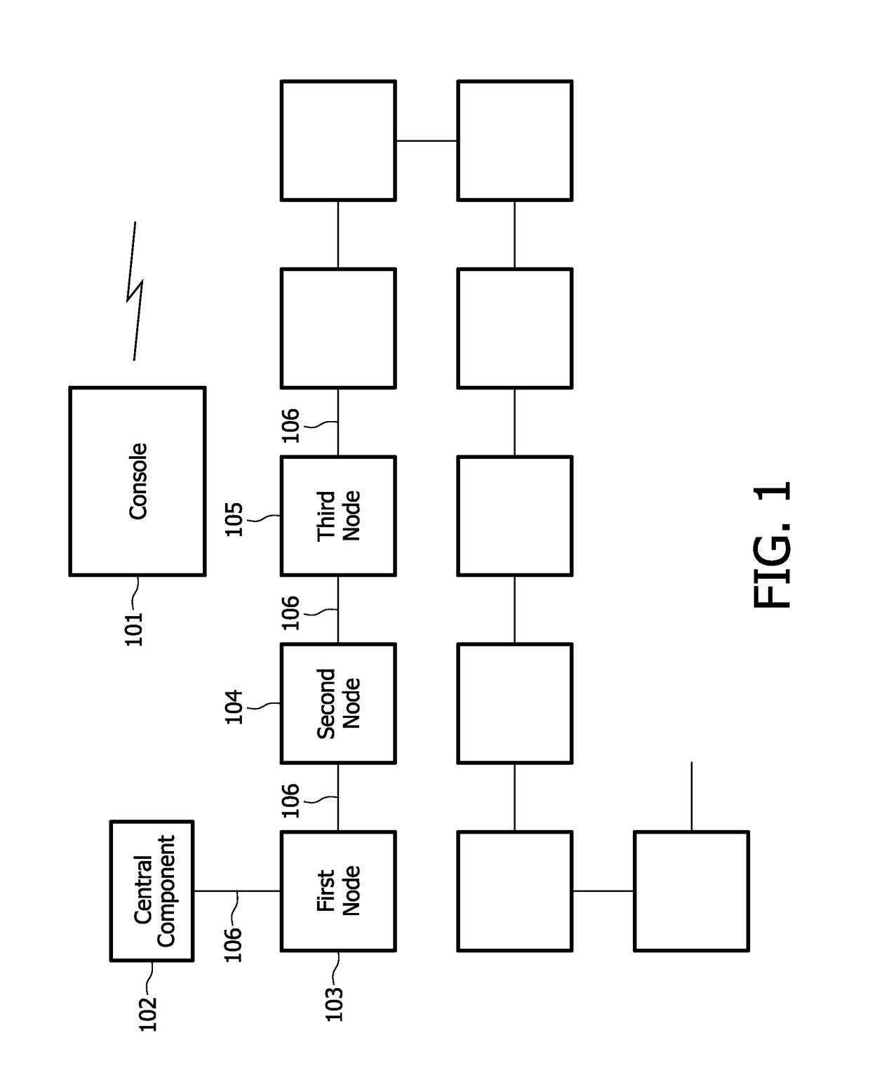
[0044]FIG. 1 is a schematic drawing of an example of a wireless communication local area network. The network comprises a console 101 and a plurality of nodes 103, 104, 105, etc. The console 101 exchanges information with the nodes and controls the nodes by communicating with them. Each of the nodes may operate one or a plurality of electronic devices, for example, each node may control one lamp or a group of lamps; the console may control the electronic devices by sending control signals to the nodes; while the console may acquire the status or various parameters of the electronic devices from the information transmitted by the nodes.

[0045]It is hard to obtain the accurate physical locations of the nodes through wireless communication only; while manually obtaining the physical locations of the respective nodes is obviously difficult. In this embodiment, the technical solution disclosed in the present invention is adopted to solve this problem. As FIG. 1 shows, the respective nodes...


PUM


Abstract

A method and apparatus for allocating channels for a wireless communication local area network are presented. A system includes a console and a plurality of nodes controllable by the console through wireless communication. At least two nodes are connected in series, each of the nodes being configured to transmit signals in turn. A trigger signal is sent to a first node, and a first response signal sent by the first node in response to the trigger signal to determine that the first node is available. A first wireless channel is allocated for wireless communication between the console and the first node, and for sending information including the allocation of the first wireless channel to the first node, whereupon the first node transmits the trigger signal to a second node adjacent to the first node after confirming that the allocation of the first wireless channel has been completed.

Description

TECHNICAL FIELD[0001]The present invention relates to a channel allocation method and apparatus for use in a Wireless communication local area network, in particular to a channel allocation method and apparatus for use in a wireless communication local area network used for illumination control.BACKGROUND ART[0002]Wireless communication local area networks have been increasingly widely used in recent years, especially combined with techniques in other fields in order to develop wireless control local area networks that meet different demands, bringing people great convenience. At the same time, however, these networks bring with them various requirements and problems.[0003]For example, lighting systems controlled by wireless communication techniques have seen a major development in recent years. These lighting networks are usually centrally controlled, allowing a user to achieve various kinds of integral effects in real time by controlling respective nodes. An important feature of s...

Claims


Application Information

Patent Timeline
Patent Type & Authority Patents(United States)
IPC IPC(8): H04B7/00H05B37/02H04W72/04H04W84/12
CPCH05B37/0272H04W84/12H04W72/04H05B47/19
Inventor QIAN, XUECHENG
Owner SIGNIFY HLDG BV
Learn More