Aircraft energy indicator generating system, device, and method

a technology of energy indicator and generation system, applied in the direction of process and machine control, instruments, navigation instruments, etc., can solve the problems of system not being able to maintain the descent speed, reducing speed, and reducing speed, so as to improve the situational awareness of pilots

Active Publication Date: 2017-11-14
ROCKWELL COLLINS INC
View PDF6 Cites 5 Cited by
  • Summary
  • Abstract
  • Description
  • Claims
  • Application Information

AI Technical Summary

Benefits of technology

[0007]The embodiments disclosed herein are directed to a system, device, and method for generating an energy indicator that is presentable to a pilot. The indicator could be used in conjunction with the FID path to enhance situational awareness of a pilot by informing him or her whether excess energy will need to be bled off or a shortage of energy will need to be compensated by adding engine thrust.

Problems solved by technology

An autothrottle system may increase the speed of the aircraft by “adding throttle” (i.e., increasing engine thrust) and may decrease the speed by retarding the throttle without pilot intervention; however, the system may not decrease the throttle past a defined idle setting for the engines and, therefore may not reduce speed without pilot intervention of imparting “drag” through, for instance, the use of speed brakes if a speed brake system is installed.
If the actual VDP path on which the aircraft is flying is too steep and the drag is insufficient, the system may not be able to maintain the descent speed.
When the VPA is a fixed, three degree angle, the amount of throttle required to maintain the VDP is typically above idle.
The excess fuel consumption—the amount of fuel needed to power the engines above idle—increases operating costs as fuel is wasted in light of the relatively large amount of total energy available to the aircraft during descent.

Method used


Image

  • Aircraft energy indicator generating system, device, and method
  • Aircraft energy indicator generating system, device, and method
  • Aircraft energy indicator generating system, device, and method

Examples


Embodiment Construction

[0028]In the following description, several specific details are presented to provide a thorough understanding of embodiments of the inventive concepts disclosed herein. One skilled in the relevant art will recognize, however, that the inventive concepts disclosed herein can be practiced without one or more of the specific details, or in combination with other components. In other instances, well-known implementations or operations are not shown or described in detail to avoid obscuring aspects of various embodiments of the inventive concepts disclosed herein.

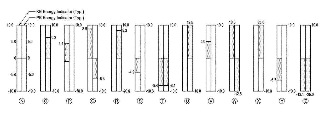
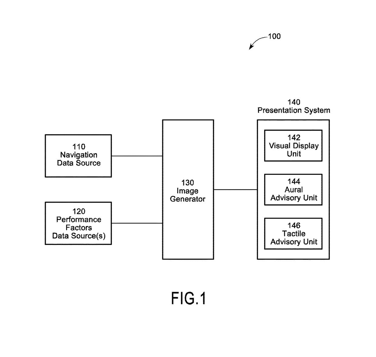
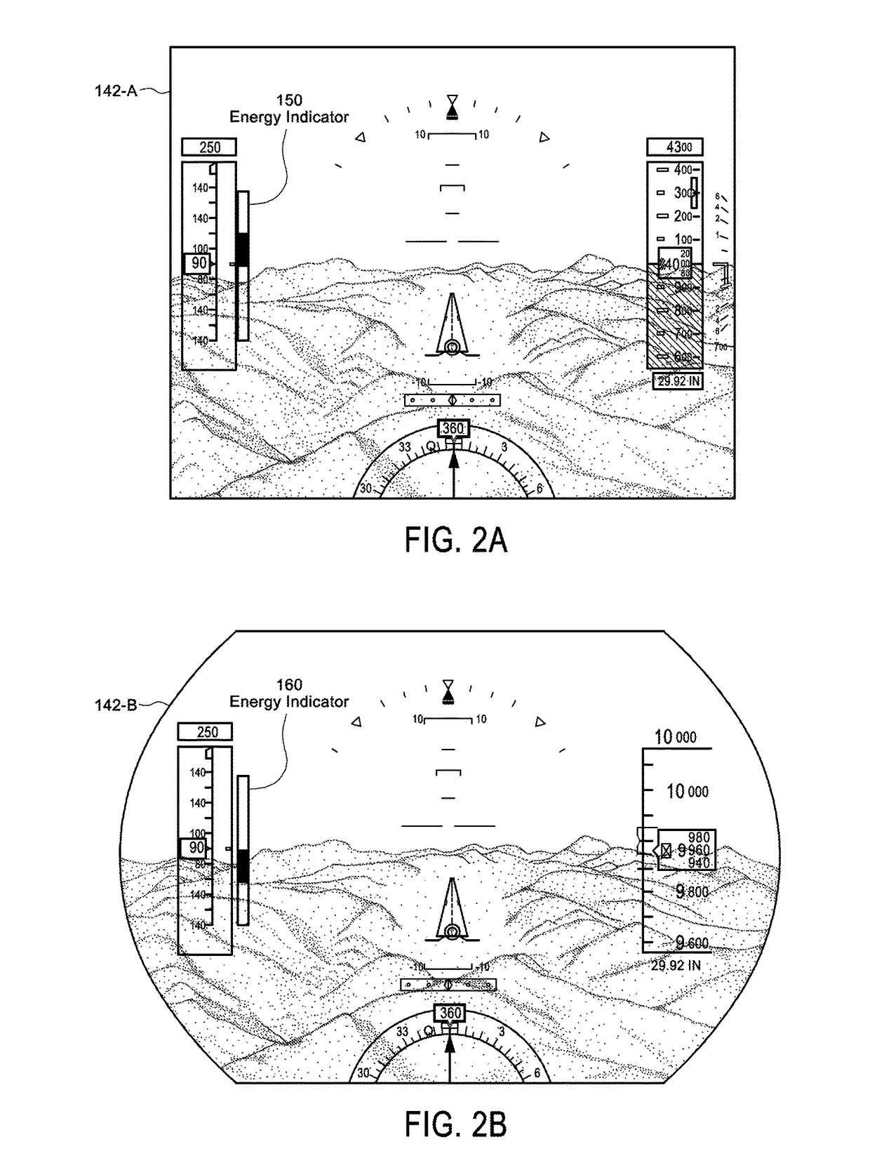
[0029]FIG. 1 depicts a functional block diagram of an embodiment of an energy indicator generating system 100 suitable for implementation of the techniques described herein. The functional blocks of the system 100 include a navigation data source 110, a performance factors data source 120, an image generator (IG) 130, and a presentation system 140.

[0030]The navigation data source 110 could include any source(s) which provides n...


PUM


Abstract

Present novel and non-trivial system, device, and method for generating an aircraft energy indicator(s) is disclosed. The energy indicator generating system is comprised of one or more sources of aircraft performance factors data, an image generator (IG), and a presentation system. The IG may be configured to receive the aircraft performance factors data representative of at least aircraft altitude and speed; determine descent path data as a function of at least the aircraft performance data; determine target aircraft energy data as a function of at least the descent path data; determine actual energy data as a function of at least the aircraft performance data; and generate presentation data as a function of the target energy data and the actual energy data, where the presentation data is representative of one or more images of an aircraft energy indicator presentable to a viewer.

Description

BACKGROUND[0001]Field of the Inventive Concepts[0002]The inventive concepts disclosed herein pertain generally to the field of aircraft display units that present information to the pilot of an aircraft.[0003]Description of the Related Art[0004]A vertical descent path (VDP) of an aircraft's flight path is typically assigned a fixed vertical path angle (VPA). Perhaps the most common VPA is three degrees although this may differ due to, for instance, altitude constraints built into the VDP. When it comes time to fly the VDP, an aircraft system(s) may be configured (or programmed) to control the aircraft pitch so that the aircraft follows the VDP while maintaining a descent speed target through movement of the aircraft throttle(s). An autothrottle system may increase the speed of the aircraft by “adding throttle” (i.e., increasing engine thrust) and may decrease the speed by retarding the throttle without pilot intervention; however, the system may not decrease the throttle past a defi...

Claims


Application Information

Patent Timeline
Patent Type & Authority Patents(United States)
IPC IPC(8): G05D1/00B64D45/08G05D1/06B64D43/00B64D47/02
CPCB64D45/08B64D43/00B64D47/02G01C23/00
Inventor OGDEN, COLLIN D.MICKELSON, BRADLEY R.KOLEK, KIRK A.
Owner ROCKWELL COLLINS INC
Why Eureka
Try Eureka