Solar thermal collector and building accessory structure

a solar thermal collector and building technology, applied in the direction of collector thermal insulation, heat collector mounting/support, light and heating apparatus, etc., can solve the problems of limiting the applicability and design flexibility of solar thermal collectors, and the structure of current solar thermal collectors is usually not rigid, so as to achieve less overall thickness, improve design flexibility, and more rigid structure

Inactive Publication Date: 2017-11-14
HSIU LIN PENG
View PDF23 Cites 1 Cited by
  • Summary
  • Abstract
  • Description
  • Claims
  • Application Information

AI Technical Summary

Benefits of technology

[0007]The disclosure provides a solar thermal collector and a building accessory structure. When compared with conventional solar thermal collectors, the provided solar thermal collector has more rigid structure and better design flexibility. It also has less overall thickness and thus less wind resistance. As a result, the provided solar thermal collector is advantageous to be applied to a building as an accessory structure of the building.
[0025]Based on the above, the provided solar thermal collector allows the heat transfer fluid to directly contact and flow through the heat absorbing plate, which means the solar thermal collector of the disclosure has a much larger heat exchange area than conventional collectors. Moreover, in the provided solar thermal collector, the heat conductivity of the heat absorbing plate is more than 30 times greater than the heat conductivity of the heat insulating plate. With such configuration, the thermal energy of sunlight can be efficiently transferred to the heat transfer fluid through a large contact area of the heat absorbing plate, which has high heat conductivity. Meanwhile, the heat insulating plate providing favorable thermal insulation can effectively reduce heat loss of the provided solar thermal collector. In addition, the heat insulating plate of the disclosure is made of composite material that is light in weight, strong in structural strength and low in heat loss rate. Therefore, the thickness of the solar thermal collector profile and the collector frame can be effectively reduced without sacrificing the structural strength and the thermal insulation performance. Furthermore, due to the reduction of the solar thermal collector's overall thickness, the wind resistance is lowered to improve the applicability and design flexibility when the solar thermal collector is integrated with the building.
[0026]In addition, different from conventional collectors that can only be installed on rooftops, the solar thermal collector of the disclosure can be framed as building accessory structures that can be applied to building external areas, such as a balcony, window, or patio, to serve as railings, louvers, or patio shade structures. Therefore, the design flexibility can significantly improve the applicability when the solar thermal collector is integrated with the building.

Problems solved by technology

However, the structures of current solar thermal collectors usually are not rigid and the installation requires attaching the collectors to existing building exterior structures, rather than become part of the building exterior structure.
In addition, the bulky size and thickness of current solar thermal collectors limits the applicability and design flexibility of the solar thermal collector in the field of building integrated solar thermal (BIST).

Method used


Image

  • Solar thermal collector and building accessory structure
  • Solar thermal collector and building accessory structure
  • Solar thermal collector and building accessory structure

Examples


Embodiment Construction

[0038]It is to be understood that the foregoing and other technical contents, features, and advantages are intended to be described more comprehensively by providing embodiments accompanied with figures hereinafter. In the following embodiments, wording used to indicate directions, such as “up,”“down,”“front,”“back,”“left,” and “right,” merely refers to directions in the accompanying figures. Therefore, the directional wording is used to illustrate rather than limit the invention. Moreover, the same or similar reference numerals represent the same or similar elements in the following embodiments.

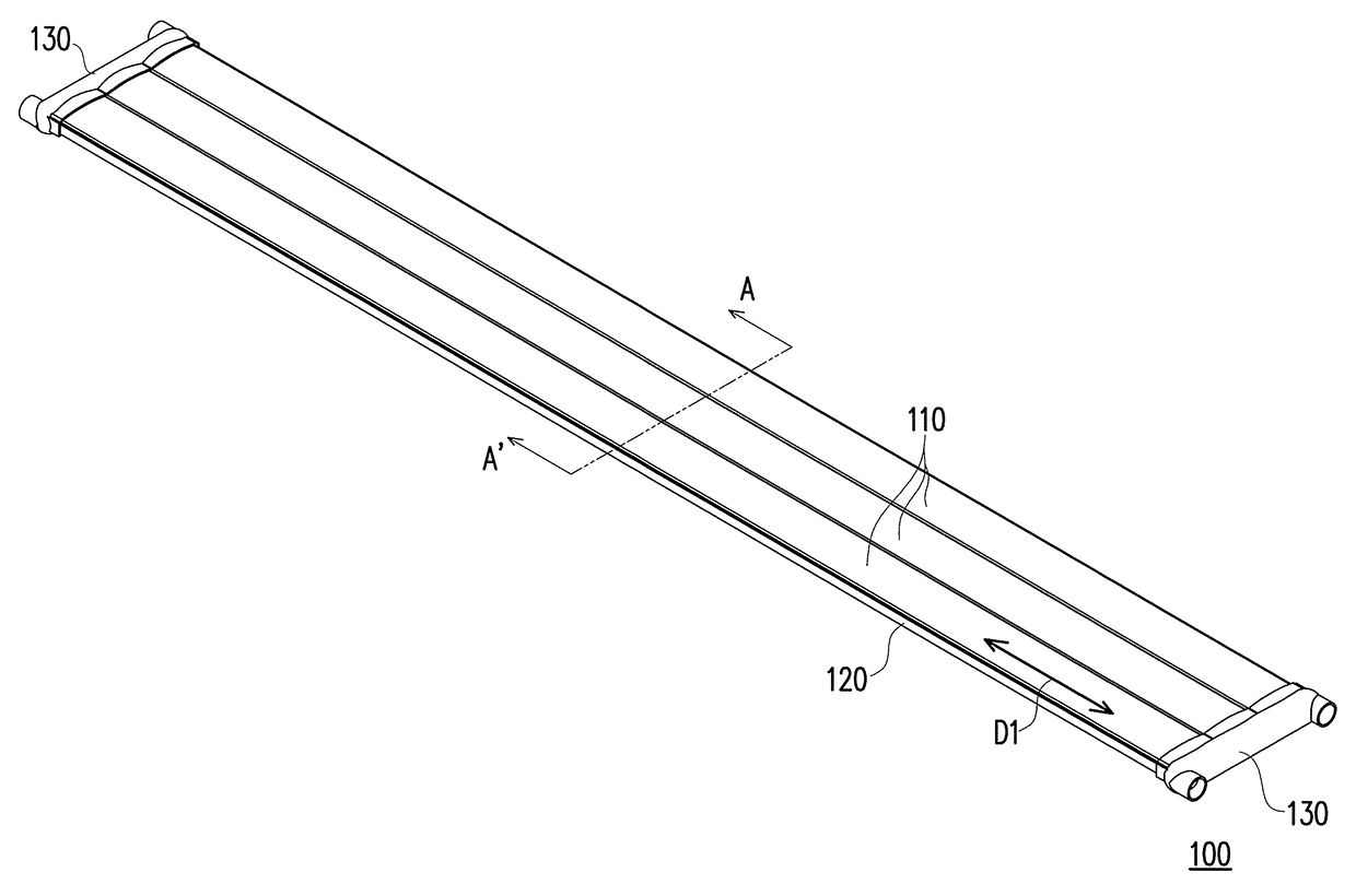
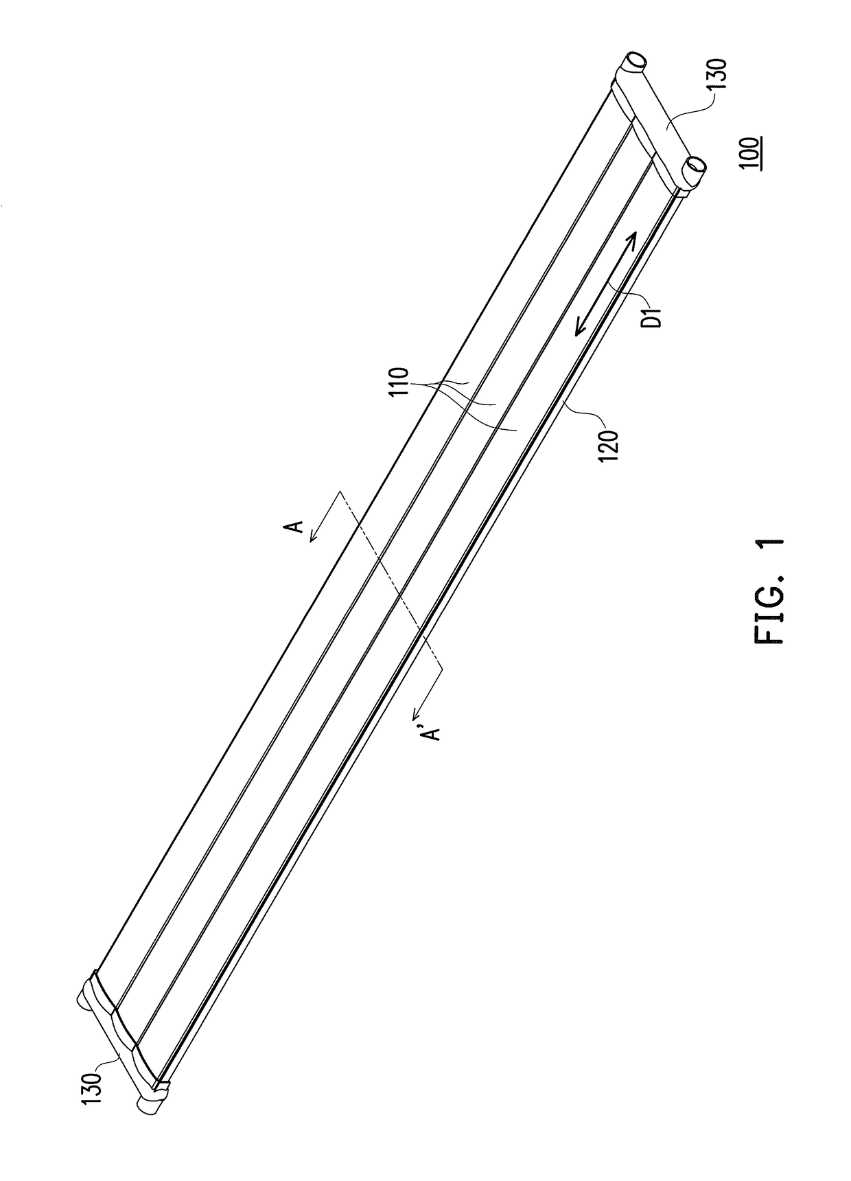
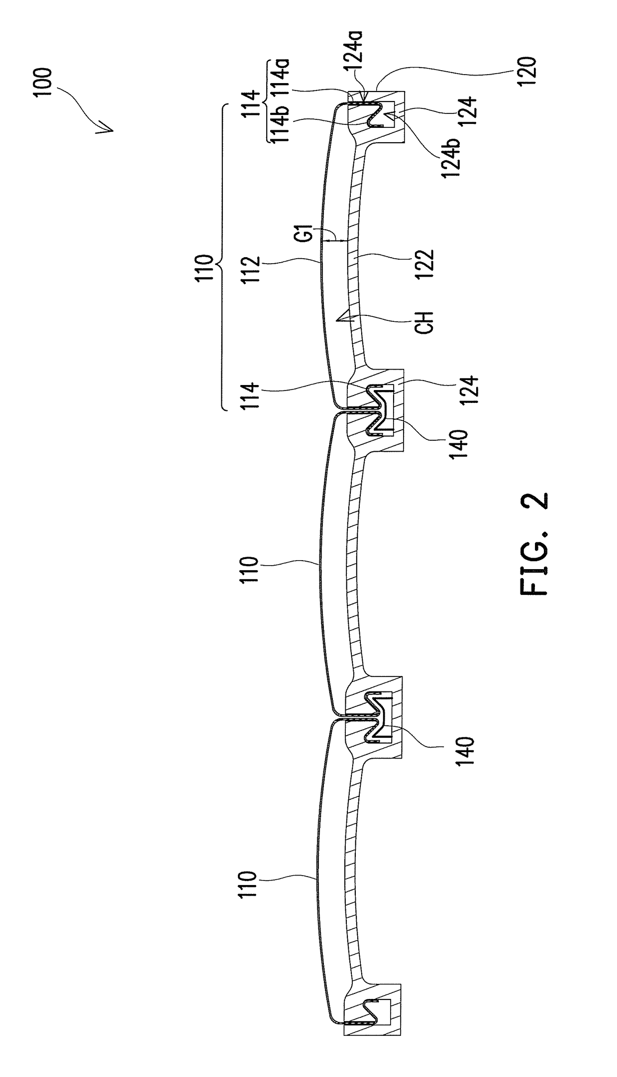
[0039]FIG. 1 is a schematic view of a solar thermal collector according to an embodiment of the invention. FIG. 2 is a schematic cross-sectional view of the solar thermal collector of FIG. 1 along the line A-A′. With reference to FIG. 1 and FIG. 2, in this embodiment, a solar thermal collector 100 includes at least one heat absorbing plate 110 and at least one heat insulating plate 120. The ...


PUM

PropertyMeasurementUnit
pressureaaaaaaaaaa
pressureaaaaaaaaaa
Young's modulusaaaaaaaaaa

Abstract

A solar thermal collector and an accessory structure of a building are provided. The solar thermal collector includes at least one heat absorbing plate and at least one heat insulating plate. Each of the heat absorbing plate includes at least one first slab and first engaging parts connected with the first slab. Each of the heat insulating plate includes at least one second slab and second engaging parts connected with the second slab. The first engaging parts are respectively engaged with the second engaging parts, and a gap is maintained between the first slab and the second slab to define a heat collecting channel, through which a heat transfer fluid flows between the heat absorbing plate and the heat insulating plate. A heat conductivity of the heat absorbing plate is at least 30 times greater than a heat conductivity of the heat insulating plate.

Description

CROSS-REFERENCE TO RELATED APPLICATION[0001]This application claims the priority benefit of China patent application serial no. 201410647808.9, filed on Nov. 13, 2014. The entirety of the above-mentioned patent application is hereby incorporated by reference herein and made a part of the specification.BACKGROUND OF THE INVENTION[0002]Field of the Invention[0003]The invention relates to a building-integrated energy collector and an accessory structure of a building. Specifically, the invention relates to a building-integrated solar thermal collector and a building accessory structure using the solar thermal collector.[0004]Description of Related Art[0005]With the rising awareness of environmental conservation, the public is paying more attention to the concepts of energy saving and reducing carbon emissions. The technologies of utilizing renewable energy have gained worldwide attention. In terms of renewable energy, solar energy is widely available. Unlike other energy sources, such ...

Claims


Application Information

Patent Timeline
Patent Type & Authority Patents(United States)
IPC IPC(8): F24J2/04F24J2/46F24J2/20F24J2/51F24J2/05F24J2/48F24J2/24F24S10/40F24S10/50F24S10/70
CPCF24J2/0433F24J2/0427F24J2/0444F24J2/05F24J2/20F24J2/202F24J2/204F24J2/205F24J2/207F24J2/4647F24J2/4652F24J2/485F24J2/487F24J2/51F24J2/515F24J2/045Y02E10/44F24J2/24F24J2002/467Y02B10/20F24S10/40F24S10/50F24S10/502F24S10/503F24S10/504F24S10/505F24S20/62F24S20/67F24S20/69F24S70/225F24S70/25F24S70/30F24S80/30F24S80/60F24S80/65F24S2025/6007F24S10/70F24S20/63
Inventor PENG, HSIU-LINCHEN, YU-YAO
Owner HSIU LIN PENG
Why Eureka
Try Eureka