
Circuit arrangement for monitoring temperature and calorimetric mass flowmeter

a technology of calorimetric mass flowmeter and circuit arrangement, which is applied in the direction of instruments, using electrical/magnetic means, liquid/fluent solid measurement, etc., can solve the problems of limited surface temperature of electronic components arranged in the area at risk of explosion and limited power dissipation. to a relatively small valu

Inactive Publication Date: 2017-11-21
KROHNE MESSTECHNICK GMBH & CO KG
View PDF12 Cites 13 Cited by
  • Summary
  • Abstract
  • Description
  • Claims
  • Application Information

AI Technical Summary

Benefits of technology

The present invention provides a circuit arrangement for a calorimetric flowmeter that ensures safe monitoring of the temperature of an electronic component that is exposed to electric current. The arrangement uses information about the temperature of the heating component from the resistance value of the electronic component to safely shut down the power supply and prevent further heating. The arrangement includes a comparator that interrupts the flow of current when the temperature exceeds a predetermined value, and a redundant switching device that ensures the electronic component is not overheated and prevents explosions. The invention provides improved safety and reliability for calorimetric flowmeters that use electronic components.

Problems solved by technology

Additionally, it also applies that the surface temperature of the electronic components arranged in the area at risk of explosion is limited in order to counter the risk of explosion due to hot surfaces.
Due to a relatively high thermal resistance in some components—such as the heating element of calorimetric mass flowmeters—the temperature limitation leads to the power dissipation being limited to a relatively small value.

Method used


Image

  • Circuit arrangement for monitoring temperature and calorimetric mass flowmeter
  • Circuit arrangement for monitoring temperature and calorimetric mass flowmeter
  • Circuit arrangement for monitoring temperature and calorimetric mass flowmeter

Examples


Embodiment Construction

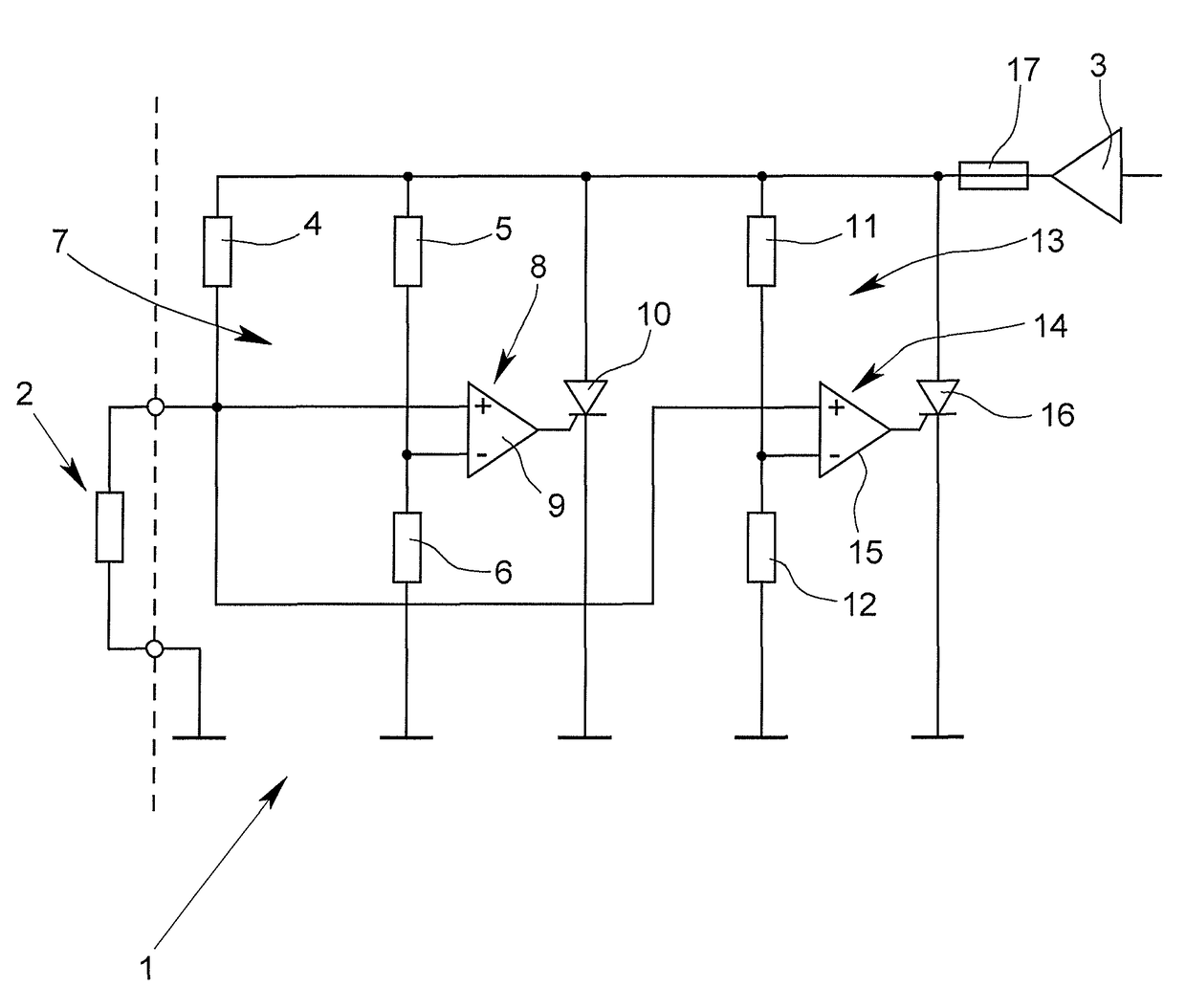
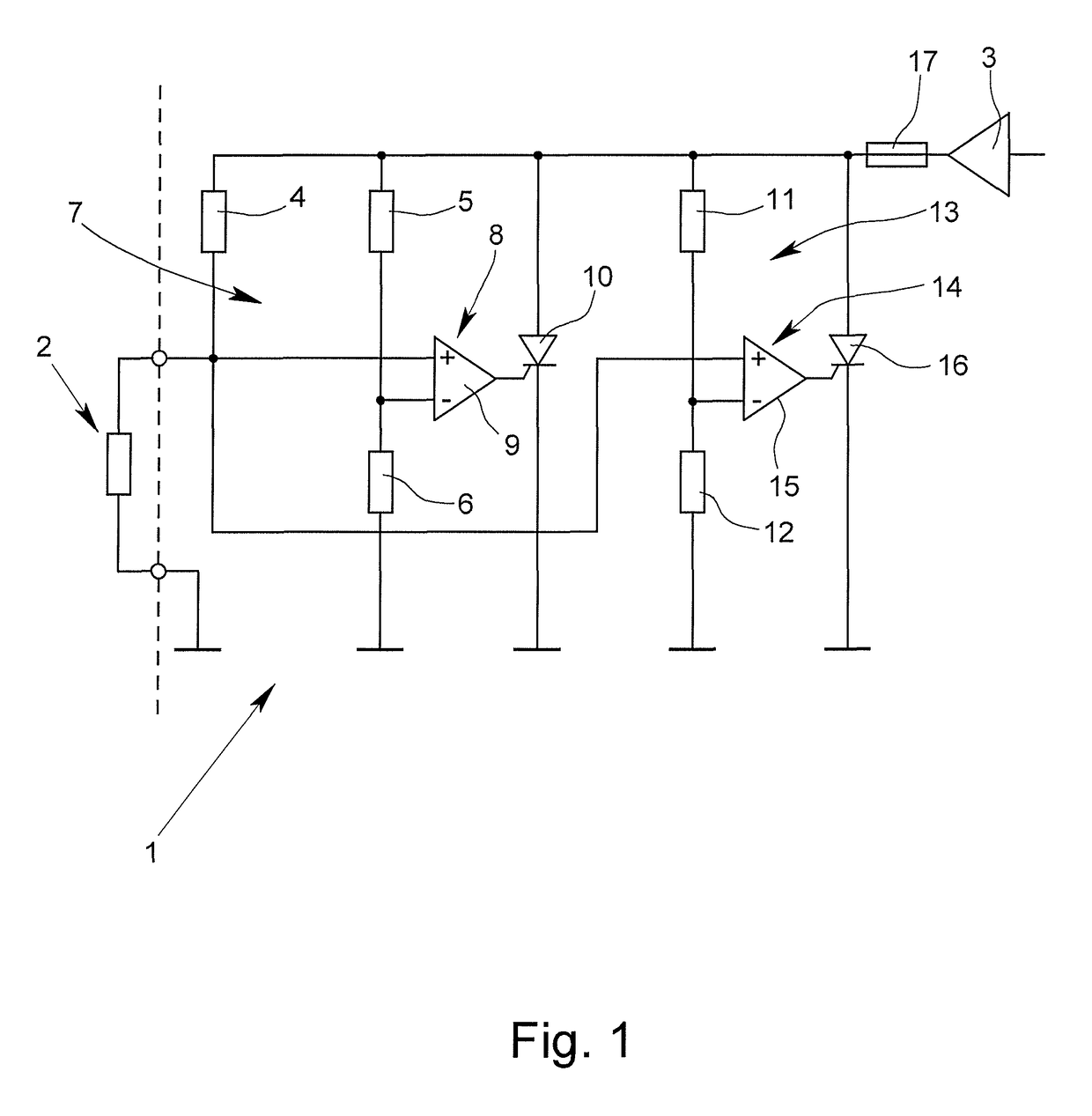
[0056]A circuit arrangement 1 is schematically represented in FIG. 1, in which the temperature of an electronic component 2 is monitored and in which it is ensured that a certain specified temperature value is not exceeded.

[0057]When used in areas at risk of explosion, it is partially necessary to make sure that temperatures are not reached in a component that could lead to a medium igniting in the corresponding area.

[0058]Such an increase in temperature could arise in the illustrated arrangement in that the electronic component 2, which is considered in the following to be an electric resistance element, heats up after impingement with electric current from a voltage source 3.

[0059]The electronic component 2 is thus at least temporarily electrically connected to the voltage source 3 and is at least temporarily impinged with an electric current from the voltage source 3. The circuit arrangement 1 is used thereby for the purpose of interrupting the power supply in the case that the e...


PUM

PropertyMeasurementUnit
surface temperatureaaaaaaaaaa
temperatureaaaaaaaaaa
electric currentaaaaaaaaaa

Abstract

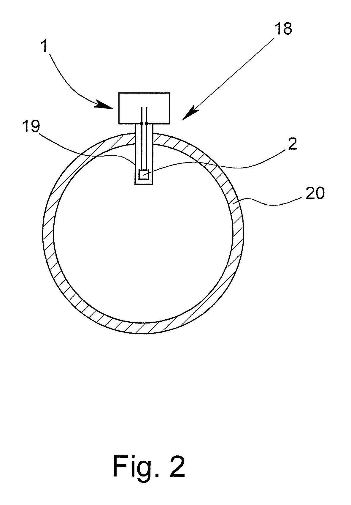
A circuit arrangement (1) for monitoring the temperature of an electronic component (2), which, in particular, can be impinged with an electric current and can be connected to at least one voltage source (3). The circuit arrangement is able to guarantee safe monitoring of the temperature of an electronic component impinged with electric current by the electronic component (2) being part of at least one Wheatstone bridge (7) and by at least one switching device (8) being provided that influences the impingement of the electronic component (2) with electric current on the basis of a bridge transverse voltage of the Wheatstone bridge (7). Additionally, circuit arrangement (1) is well suited for use in a calorimetric mass flowmeter (18).

Description

BACKGROUND OF THE INVENTION[0001]Field of the Invention[0002]The invention relates to a circuit arrangement for monitoring temperature of at least one electronic component, which can be impinged with electric current and can be connected to at least one voltage source. Furthermore, the invention relates to a calorimetric mass flowmeter having at least one electronic component, which, in particular, can be impinged with electric current and can be connected to at least one voltage source.[0003]Description of Related Art[0004]In modern process automation, measuring devices or actuators are also used in areas at risk of explosion. This makes it necessary, in particular, that certain voltage, current or temperature values are not exceeded by the components used.[0005]Thus, for example, the electric sensor systems for use in areas at risk for explosion are designed in the ignition protection category “intrinsic safety”. Hereby, intrinsic safety means that it is ensured that even in the c...

Claims


Application Information

Patent Timeline
Patent Type & Authority Patents(United States)
IPC IPC(8): G01F1/69G01F1/688G01F1/698G01K7/20G01F1/696G01K7/24
CPCG01F1/69G01F1/6888G01K7/24G01F1/698G01K7/20G01F1/696
Inventor LEHMKUHL, JURGENKUBE, JORG
Owner KROHNE MESSTECHNICK GMBH & CO KG
Learn More