Force sensor for manually operated or pneumatic presses

a technology of force sensor and pneumatic press, which is applied in the direction of force/torque/work measurement apparatus, measurement devices, instruments, etc., can solve the problem of higher overall cost, and achieve the effect of low construction height and low manufacturing cos

Active Publication Date: 2017-11-21
KISTLER HLDG AG
View PDF9 Cites 8 Cited by
  • Summary
  • Abstract
  • Description
  • Claims
  • Application Information

AI Technical Summary

Benefits of technology

[0007]It is an object of the present invention to describe a force sensor with a central axis of the type described above for measuring axially occurring forces in manually operated or pneumatic presses up to 60 kN which has a lower constructional height but overall low manufacturing costs. In addition, it should also be able to measure forces up to, preferably up to 12 kN.
[0013]The constructional height is reduced by forming in the nut or the bolt head section, respectively, means for mounting a clamping tool in the form of a center mount for a sliding fit. This is, for example, provided with a tolerance of H7+−8.018 at a diameter of 14 mm to ensure a H7 / g6 sliding fit with minimal play. Thus, a tool equipped with a corresponding locating bolt can be arranged in the desired center mount and can be inserted with its bolt in the force sensor in a centered manner. Attachment can be achieved by using a set screw that is accessible from the outside. In this way, mounting and dismounting of the tool is very easy. Furthermore, mounting always ensures a centric and tilt-safe accommodation of the tool.

Problems solved by technology

Although the embodiment with the integrated sensor has a lower constructional height, its overall costs are higher as compared to the embodiment with a separate sensor because conventional sensors cannot be used.

Method used


Image

  • Force sensor for manually operated or pneumatic presses
  • Force sensor for manually operated or pneumatic presses
  • Force sensor for manually operated or pneumatic presses

Examples


Embodiment Construction

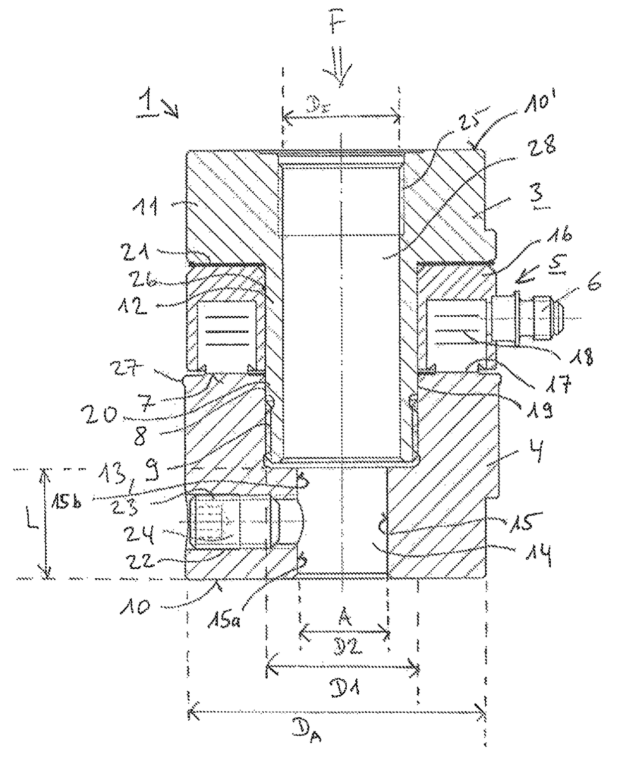
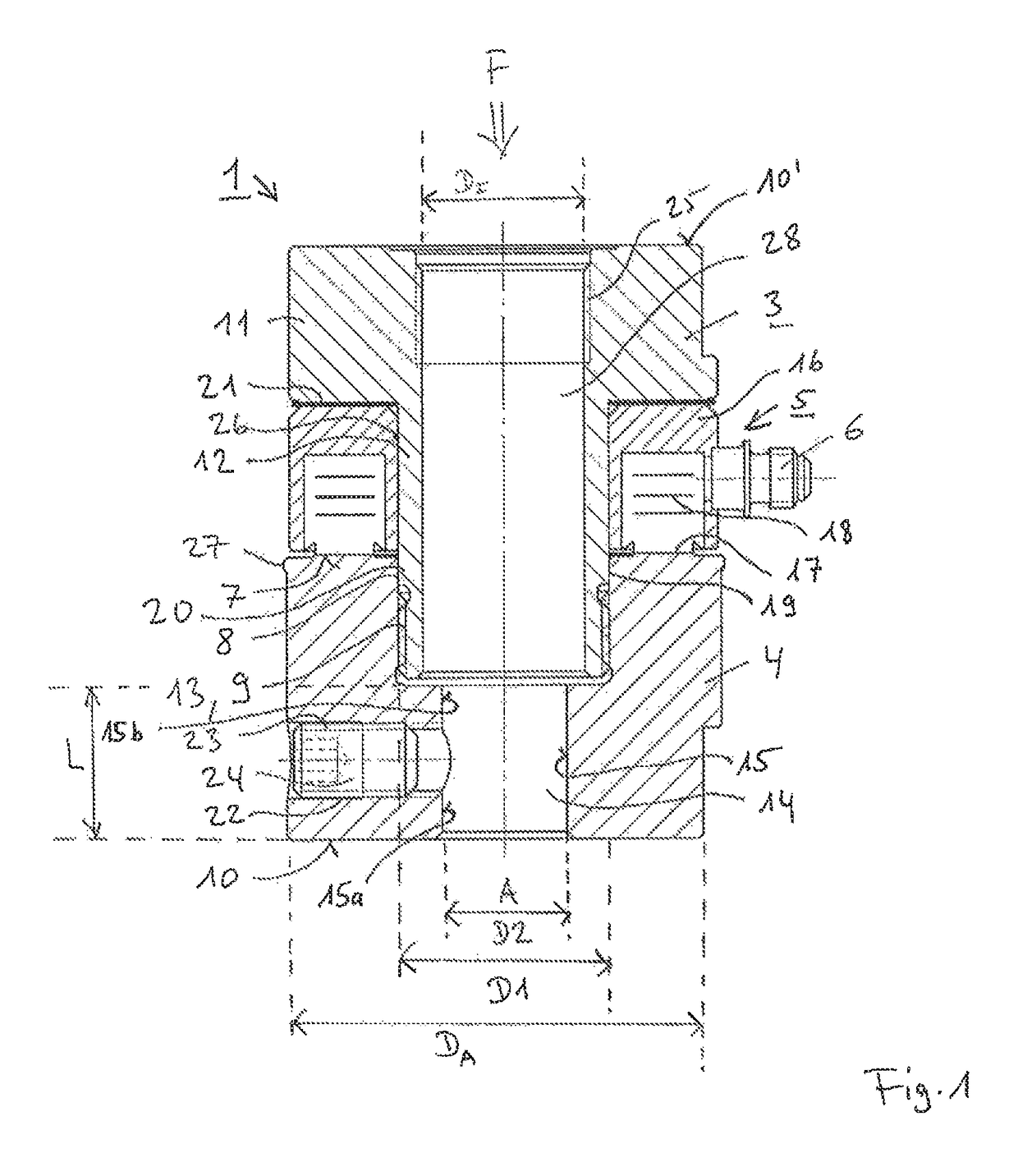
[0020]FIG. 1 a shows a force sensor 1 with an outer diameter DA and having a central axis A for the measurement of axially occurring forces F in manually operated or pneumatic presses 2 as shown in FIG. 4, with a lower and an upper annular bearing surface 10, 10′. The force sensor 1 includes a piezoelectric force washer 5 damped between a bolt 3 and a nut 4 and having a plug connection 6. The outer diameter DA in the area of the nut 4 is essentially of the same size as in the area of the bolt 3 and the force washer 5.

[0021]The nut 4 includes an inner end face 7 with a first bore 8 extending axially from the inner end face 7 and having a first diameter D1 with an internal thread 9. Furthermore, according to a first embodiment of the nut 4, the lower, annular bearing surface 10 of the sensor 1 is defined normal to the central axis A. The bolt 3 includes a head portion 11 as well as a hollow preloading shank 12 with an inner diameter DI in a central bore 28. The hollow preloading shank...


PUM

PropertyMeasurementUnit
tensile forcesaaaaaaaaaa
pressure forcesaaaaaaaaaa
forcesaaaaaaaaaa

Abstract

A force sensor for measuring axially occurring forces in manually operated or pneumatic presses has a central axis and an outer diameter and includes a bolt and a nut that preload between them a piezoelectric force washer with a plug connection. The washer has an inner end face defining a first bore having a first diameter with an internal thread. The bolt defines a throughbore with an internal diameter, a head portion and a hollow shaft defining a frontal external thread extending through the force washer and engaging the nut's internal thread. The nut or the head portion defines a second bore with a second diameter measuring smaller than the shafts internal diameter but at least one quarter of the outer diameter and at least as long as its diameter. The inner wall of the second bore defines a center mount for a sliding fit.

Description

CROSS-REFERENCE TO RELATED APPLICATIONS[0001]This application claims priority to International Application Serial No. PCT / CH2014 / 000174, filed Dec. 15, 2014, which claims priority to Swiss Application No. 2117 / 13, filed Dec. 20, 2013. International Application Serial No. PCT / CH2014 / 000174 is hereby incorporated herein in its entirety for all purposes by this reference.FIELD OF THE INVENTION[0002]The invention relates to a force sensor having a lower and an upper annular bearing surface and an outer diameter DA for measuring axially occurring forces in manually operated or pneumatic presses comprising a piezoelectric force washer with a plug connection preloaded between a bolt and a nut wherein said nut has a first bore having a first diameter with an internal thread and wherein said bolt has a head portion as well as a hollow preloading shank having an inner diameter DI and having a frontal external thread that extends through the force washer and engages the internal thread of the ...

Claims


Application Information

Patent Timeline
Patent Type & Authority Patents(United States)
IPC IPC(8): G01L1/16B30B15/00G01L5/00
CPCG01L1/16G01L5/0076G01L5/0038B30B15/0094
Inventor LEHMANN, ANDRI MICHAEL
Owner KISTLER HLDG AG
Why Eureka
Try Eureka