Eureka AIR delivers breakthrough ideas for toughest innovation challenges, trusted by R&D personnel around the world.

Side airbag with internal diffuser

Active Publication Date: 2017-11-28
AUTOLIV ASP INC
View PDF25 Cites 3 Cited by
  • Summary
  • Abstract
  • Description
  • Claims
  • Application Information

AI Technical Summary

Benefits of technology

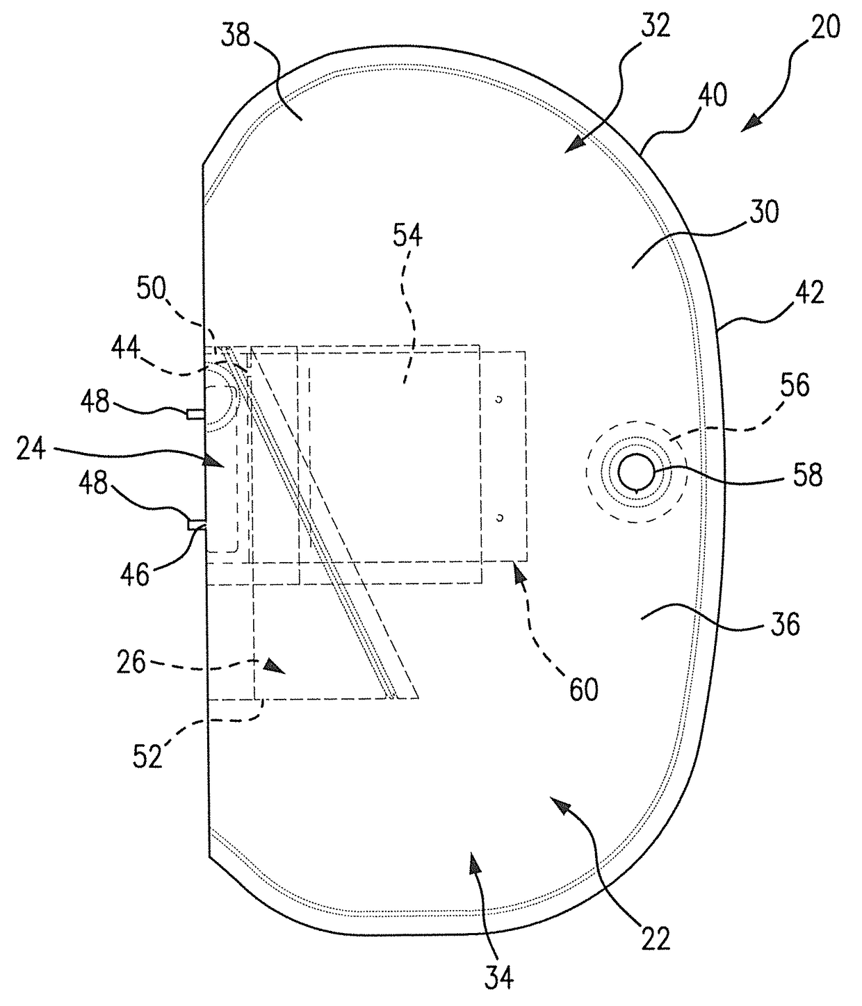
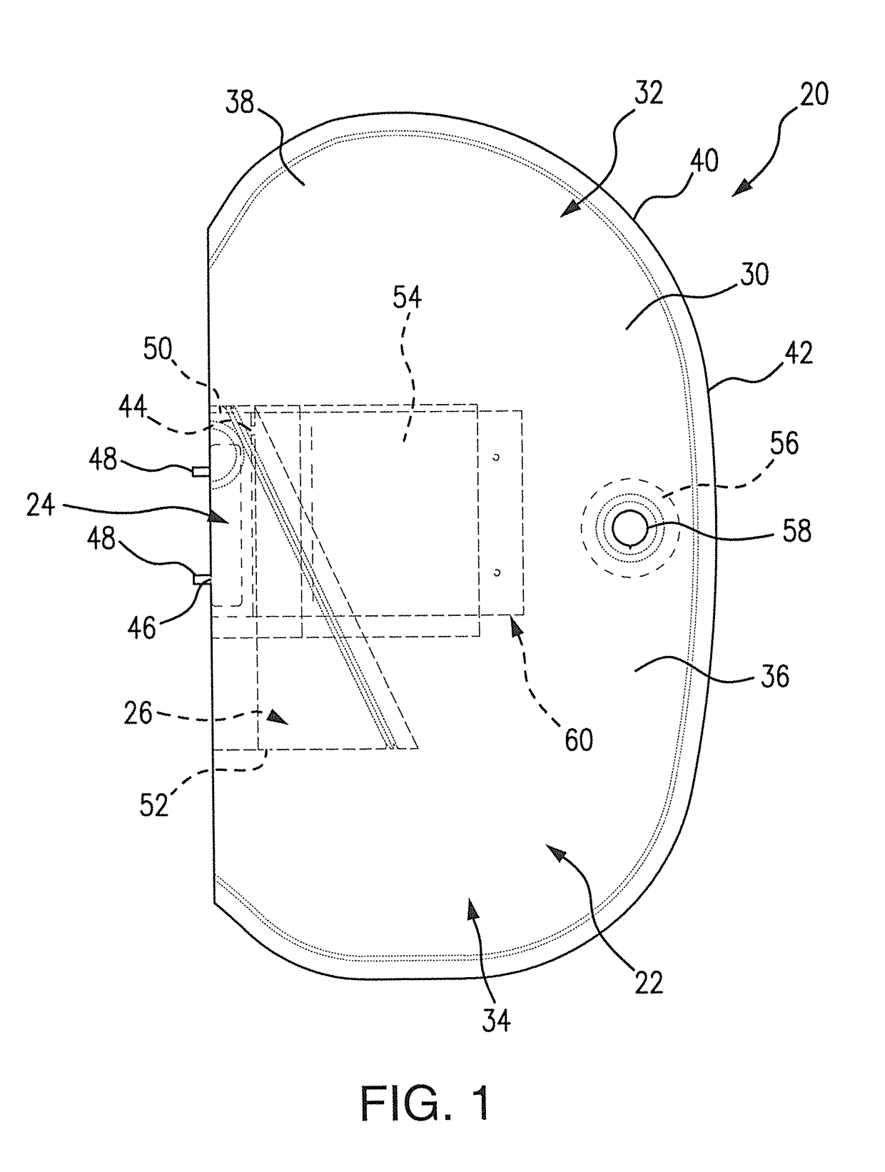
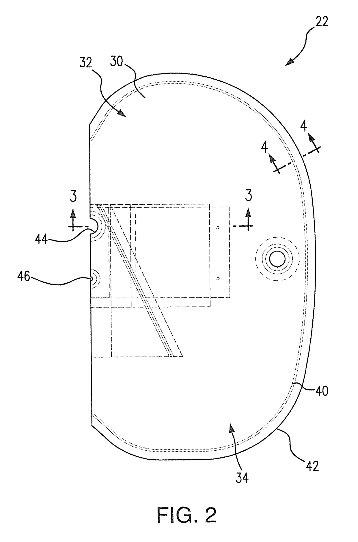
The patent describes a rear side airbag for vehicles that protects the occupant from injury in the event of a collision. The airbag has a inflatable chamber with an upper and lower portion for contact with the occupant's thorax and pelvic regions, respectively. A loop diffuser is placed around the inflator and is designed to allow more gas to flow to the lower pelvic portion of the airbag during inflation compared to the upper thorax portion. This results in a more effective and efficient airbag for protecting the occupant.

Problems solved by technology

As will be appreciated, as compared to frontal impacts and frontal airbags, side impacts or collisions such as to cause or produce the deployment of a side airbag typically result in a significantly reduced time period between the occurrence of deployment event, e.g., the vehicle collision or impact, and contact of the occupant with the deployed airbag.
Further, due to the close positioning to occupants of side airbags and the reduced time period between the occurrence of deployment event and contact of the occupant with a side airbag, the problems of out-of-position occupants can be particularly troublesome in connection with side airbags.
While increasing the volume of the airbag or decreasing the inflator generate load can act to decrease the airbag forces experienced by an OOP occupant, such approaches are generally contrary to the sought objective of providing desired occupant protection in the event of a vehicle impact.
However, the airbag industry has experienced difficulty in deploying the lower pelvic portion of the side airbag in its intended position in a sufficient time period.
If the pelvic portion of the side airbag is not positioned before significant intrusion occurs, the deploying side airbag may rebound off the armrest on the vehicle door, or otherwise be prevented from deploying in its proper position, possibly compromising the physical safety of the occupant.

Method used


Image

  • Side airbag with internal diffuser
  • Side airbag with internal diffuser
  • Side airbag with internal diffuser

Examples


examples

[0076]In this example, a truncated triangular loop diffuser such as shown in FIG. 8 was constructed. The diffuser had the dimensions listed below in TABLE 1, assuming that the opposed open ends of the diffuser take a circular shape upon deployment and inflation.

[0077]

Lay Flat LengthCircumferenceArea(mm)(mm)(mm2)Top opening4284561Bottom opening1452906692

[0078]In this example, the area of the top open end of the diffuser was 8.4% of the area of the bottom open end of the diffuser.

[0079]Thus, the invention provides new and improved side airbags and side airbag assemblies such as provide desired occupant protection while desirably reducing or minimizing the possible consequences of an OOP occupant.

[0080]In accordance with one aspect, the invention provides new and improved rear side airbags and rear side airbag assemblies such as provide desired occupant protection while desirably reducing or minimizing the possible consequences of an OOP occupant.

[0081]The invention illustratively disc...


PUM


Abstract

Side airbags to provide protection to vehicle occupants are provided. The side airbags include an outer skin forming an inflatable chamber having an upper thorax portion and a lower pelvic portion for contact with the thorax region and the pelvic region, respectively, of the associated vehicle occupant. The side airbag includes a loop diffuser for placement about an inflator disposed within the inflatable chamber. The loop diffuser has opposed first and second open ends to permit communication of inflation gas to the upper thorax portion and to the lower pelvic portion, respectively, of the inflatable chamber. The loop diffuser permits significantly greater flow of inflation gas to the lower pelvic portion as compare to flow of inflation gas to the upper thorax portion of the inflatable chamber. The first open end can be significantly smaller in cross section as compared to the second open end.

Description

BACKGROUND OF THE INVENTION[0001]Field of the Invention[0002]This invention relates generally to airbags such as used to provide impact protection for an occupant of a motor vehicle and, more particularly, to side airbags including or having an internal diffuser such as particularly suited in or for the protection of a seated vehicle occupant in the event of the occurrence of a side impact or collision.[0003]Discussion of Related Art[0004]Vehicular inflatable restraint systems, e.g., airbag systems, were developed to supplement conventional safety belts by deploying into the space between an occupant and an interior object or surface in the vehicle during a collision event. The airbag acts to decelerate the occupant, thus reducing the possibility of injury to the occupant caused by unintended contact with the interior of the vehicle.[0005]Many typical airbag systems consist of several individual components joined to form an operational module. Such components generally include an ai...

Claims


Application Information

Patent Timeline
IPC IPC(8): B60R21/207B60R21/2346B60R21/26B60R21/261B60R21/231B60R21/217
CPCB60R21/2346B60R21/207B60R21/217B60R21/231B60R21/261B60R21/26B60R2021/2612B60R2021/2078B60R2021/23146B60R2021/23153B60R21/23138B60R21/239B60R2021/23509B60R2021/23576B60R2021/0044B60R2021/0055
Inventor HANKS, SCOTT THEADLIU, RUI
Owner AUTOLIV ASP INC
Why Eureka
Eureka Blog
Learn More