Single nucleotide detection method

a single nucleotide and detection method technology, applied in biochemistry apparatus and processes, laboratories, instruments, etc., can solve problems such as computational complexity and potential introduction of errors, characteristic fluctuations in current flow or resistivity, and limited speed of operation

Active Publication Date: 2017-11-28
LIGHTCAST DISCOVERY LTD +1
View PDF16 Cites 0 Cited by
  • Summary
  • Abstract
  • Description
  • Claims
  • Application Information

AI Technical Summary

Problems solved by technology

It will be appreciated that, whilst this approach can be highly automated and can generate sequence reads of high accuracy, its speed of operation is limited by the rate of the extension cycle.
This in itself can lead to computational complexities and the potential introduction of errors.
In this device, as the various individual nucleotide bases pass through the detection window they continuously block and unblock it causing ‘events’ which give rise to characteristic fluctuations in current flow or resistivity.
However its application to single nucleotide DNA sequencing is not taught.
We believe that this is a drawback as it will lead to signal-to-noise ratio problems when the emission come to be detected.
This will compromise the overall sensitivity and therefore practical applicability of the sequencer itself.
It is believed therefore that this method will also lead to signal-to-noise ratio and therefore sensitivity problems.

Method used


Image

  • Single nucleotide detection method
  • Single nucleotide detection method
  • Single nucleotide detection method

Examples


first embodiment

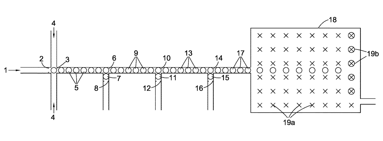
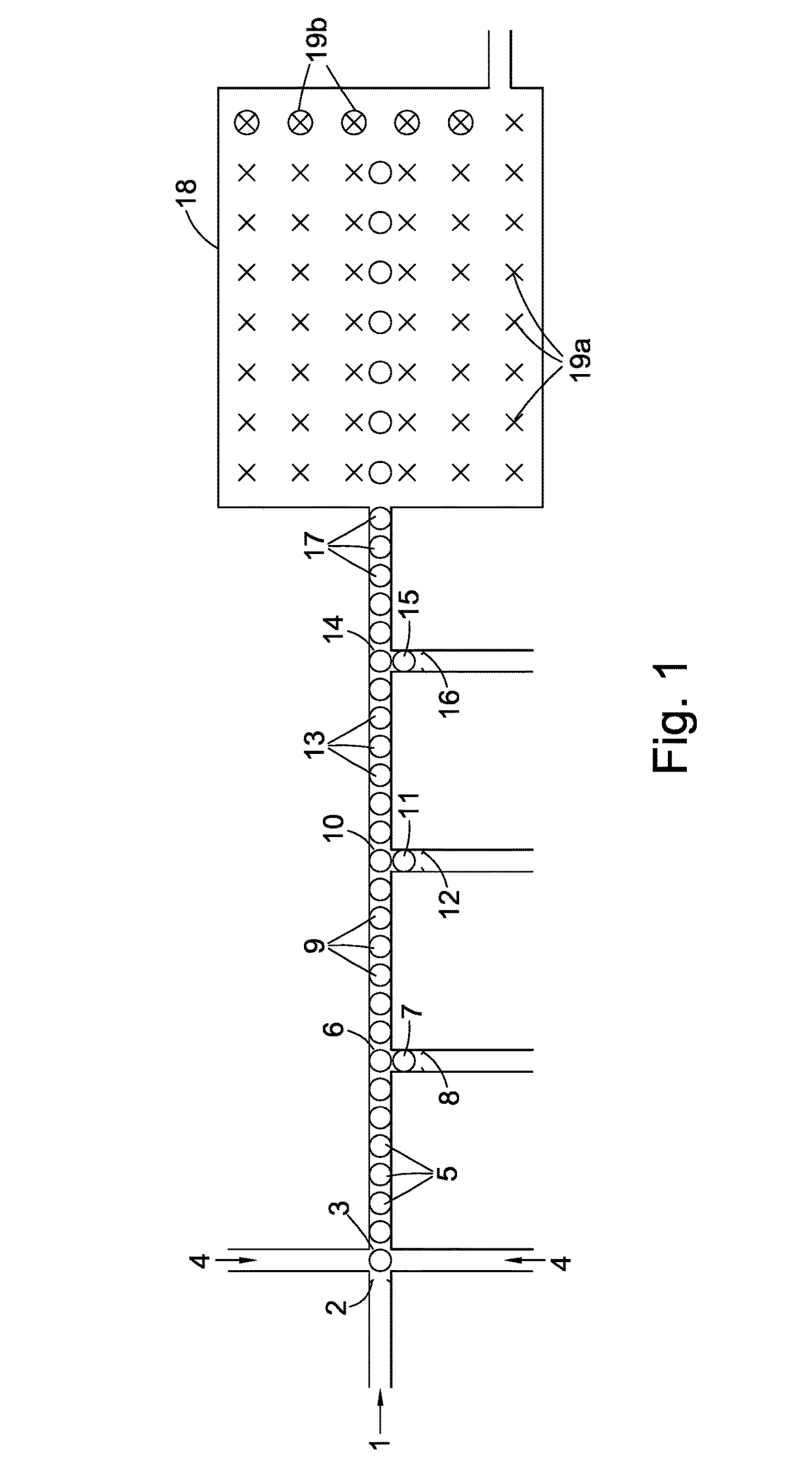
[0023]In step (2) of the method of the present invention each single nucleotide base generated in step (1) is captured by a capture system itself comprising an oligomer of nucleotide bases. Preferably, before this step is carried out the aqueous medium containing the single nucleotide bases is treated with a pyrophosphatase to hydrolyse any residual pyrophosphate to phosphate anion. In a first embodiment, the capture system comprises one of a class of pairs of first and second oligonucleotides. The first oligonucleotide in such a pair preferably comprises (a) a first double-stranded region and (b) a second single-stranded region comprised of n nucleotide bases wherein n is greater than 1 preferably greater than 5. In one sub-class, the first oligonucleotide can be regarded as having a molecular structure derived from a notional or actual single-stranded oligonucleotide precursor where the double-stranded region has been created by partially folding the 3′ end of the precursor back o...

second embodiment

[0025]In a second embodiment, the capture system comprises a class of single oligonucleotides each consisting of a single-stranded nucleotide region the ends of which are attached to two different double-stranded regions. In the capture systems of this class, the single-stranded nucleotide region is comprised of one nucleotide base only making the probe extremely selective for the detection of the target i.e. the complimentary single nucleotide base in the droplet stream.

[0026]Turning to the double-stranded oligonucleotide region(s), it is preferred that they are derived or derivable from two oligonucleotide precursors, each preferably closed looped, or from a common single-stranded oligonucleotide precursor by folding the latter's ends back on themselves to create two closed-loop oligonucleotide base regions with an intermediate gap constituting the single-stranded nucleotide region. In all cases the effect is the same; adjacent to the ends of the single-stranded nucleotide region ...


PUM

PropertyMeasurementUnit
timeaaaaaaaaaa
temperatureaaaaaaaaaa
Förster distanceaaaaaaaaaa

Abstract

A method for determining the sequence of nucleotide bases in a polynucleotide analyte is provided. It is characterized by the steps of (1) generating a stream of single nucleotide bases from the analyte by pyrophosphorolysis; (2) producing captured molecules by reacting each single nucleotide base with a capture system labelled with detectable elements in an undetectable state; (3) releasing the detectable elements from each captured molecule in a detectable state and (4) detecting the detectable elements so released and determining the sequence of nucleotide bases therefrom. The method can be used advantageously in sequencers involving the use of microdroplets.

Description

[0001]This invention relates to a method for characterising polynucleotides such as those derived from naturally occurring RNA or DNA by capturing and detecting an ordered sequence of single nucleotide bases generated therefrom by progressive pyrophosphorolysis.[0002]Next generation sequencing of genetic material is already making a significant impact on the biological sciences in general and medicine in particular as the unit cost of sequencing falls in line with the coming to market of faster and faster sequencing machines. Thus, in one such machine, a double-stranded DNA analyte is first broken down into a plurality of smaller polynucleotide fragments each of which is first adenylated on both ends of one strand so that a single-stranded first oligonucleotide can be bound to both ends of its compliment by hybridisation to the unpaired adenine base. The treated fragments so obtained are then size-selected and captured on a surface coated with bound single-stranded second oligonucle...

Claims


Application Information

Patent Timeline
Patent Type & Authority Patents(United States)
IPC IPC(8): C12Q1/68G01N35/08B01L3/00
CPCC12Q1/6869G01N35/08B01L3/502784C12Q2521/301C12Q2521/319C12Q2521/525C12Q2525/301C12Q2537/157C12Q2565/629C12Q2521/101C12Q2521/501C12Q2563/159C12Q2565/1015C12Q2565/301
Inventor FRAYLING, CAMERON ALEXANDERBALMFORTH, BARNABYSOARES, BRUNO FLAVIO NOGUEIRA DE SOUSAISAAC, THOMAS HENRYBREINER, BORISNATALE, ALESSANDRAAMASIO, MICHELEDEAR, PAUL
Owner LIGHTCAST DISCOVERY LTD
Why Eureka
Try Eureka