Device for internal cooling and pressurization of rotary engine

a technology for internal cooling and rotary engines, which is applied in the direction of engine cooling apparatus, combustion engines, machines/engines, etc., can solve the problems of adversely affecting the performance and efficiency of rotary engines, constant urgent problems, and crucial heat dissipation problems, so as to improve internal cooling and enhance the performance of rotary engines

Active Publication Date: 2017-11-28
NAT CHUNG SHAN INST SCI & TECH
View PDF2 Cites 1 Cited by
  • Summary
  • Abstract
  • Description
  • Claims
  • Application Information

AI Technical Summary

Benefits of technology

[0014]In order to overcome the shortcomings and the drawbacks of the Prior Art, the present invention provides a device for internal cooling and pressurization of rotary engine, that is capable of achieving improved internal cooling and enhanced performance of the rotary engine, through switching a plurality of valves, in an automatic control and / or remote control manner.

Problems solved by technology

Therefore, the heat dissipation problem is crucial in its performance.
In case the heat generated can not be dissipated properly, that could adversely affect the performance and efficiency of the rotary engine.
Because the rotary engine contains three chambers (the cylinder) and has the property of the small size, the heat dissipation is always an urgent problem in the development.
However, as the power required increased, the heat dissipation requirement is also rising, and the existing problems and shortages of the air cooling apparently appear.
Nevertheless, most devices with functions of water cooling or oil cooling still focus on the external cooling.
The cooling lubricant oil in bearings works on heat dissipation of rotor crank shaft, and that is insufficient.
As heat dissipation is concerned, redesign oil / lubrication system is time and cost consuming with its complexity.
Therefore, the drawback of this type of rotary engine is that, when the rotary engine is used to operate in a high flying airplane, since the air is rather cool in such a high altitude, while the ram air flow of the airplane is strong enough to take in sufficient air into the core cooling intake pipe for internal cooling, as such, the super charger connected thereto is laying idle and useless, and that constitutes quite a waste.
Further, when the rotary engine is in a high flying airplane, the atmospheric pressure is much reduced due to high altitude, such that the pressure of air taken into the engine air intake pipe is rather insufficient, to affect the combustion and the performance of the rotary engine.
As such, in this way, the rotary engine can not achieve efficient cooling and performance.
Therefore, presently, the design and performance of the rotary engine internal cooling and pressurization is not quite satisfactory, and it leaves much room for improvement.

Method used


Image

  • Device for internal cooling and pressurization of rotary engine
  • Device for internal cooling and pressurization of rotary engine
  • Device for internal cooling and pressurization of rotary engine

Examples


Embodiment Construction

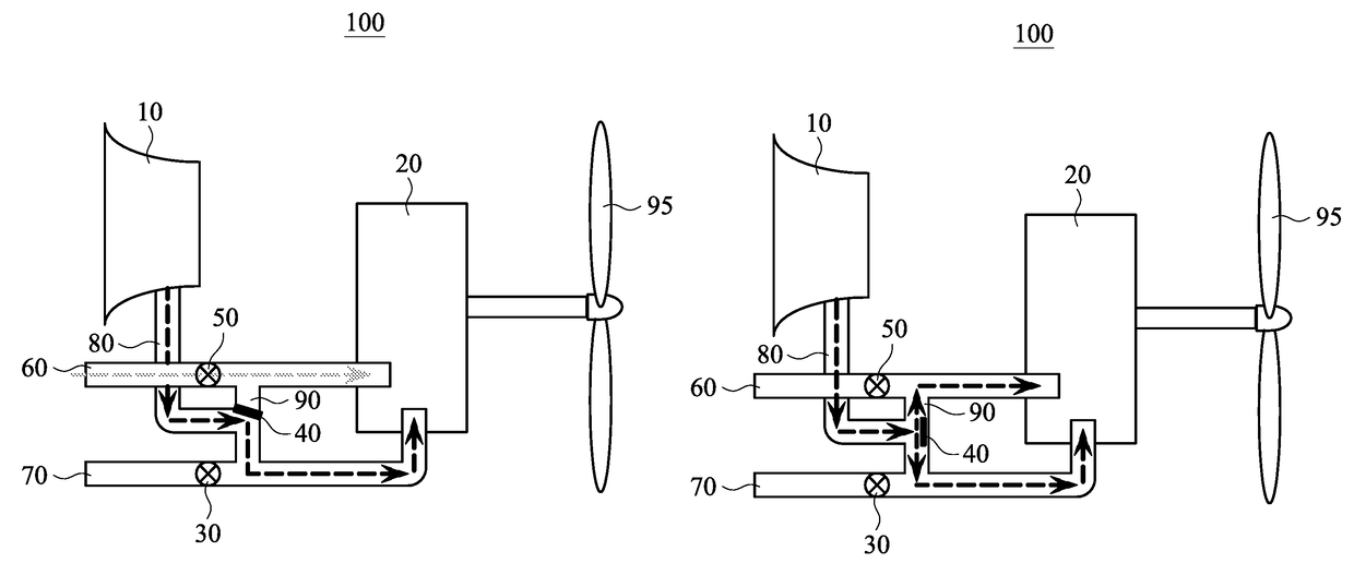
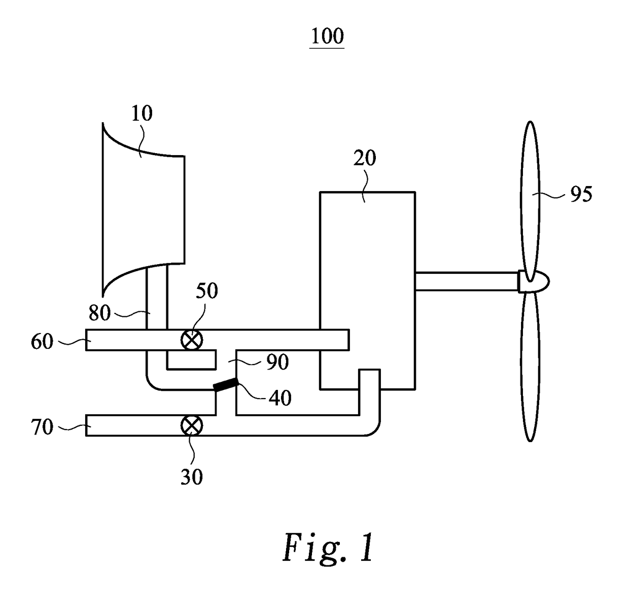
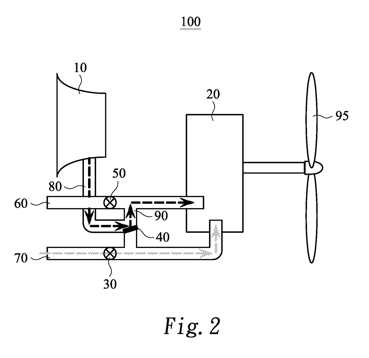
[0028]Referring to FIG. 1 is a schematic diagram of a device for internal cooling and pressurization of a rotary engine according to an embodiment of the present invention. As shown in FIG. 1, the device for internal cooling and pressurization of a rotary engine 100 includes a mechanical charger 10, a charger outlet tube 80, a core cooling intake tube 60, an engine air intake tube 70, a connection tube 90, a first valve 30, a second valve 40, and a third valve 50. The mechanical charger 10 is mounted in a ventilated place. The charger outlet tube 80 is used to dispense air, the charger outlet tube 80 has two sides, with one side coupled to the mechanical charger 10. The core cooling intake tube 60 is connected to another side of the charger outlet tube 80, and is used to dispense air. The engine air intake tube 70 is connected to another one side of the charger outlet tube 80, and is used to dispense air. The connection tube 90 is connected between the core cooling intake tube 60 an...


PUM


Abstract

A device for internal cooling and pressurization of rotary engine, comprising: a mechanical charger, a charger outlet tube, a core cooling intake tube, an engine air intake tube, a first valve, a second valve, and a third valve. The mechanical charger is mounted in a ventilated place. The charger outlet tube is used to dispense air, and the charger outlet tube has two sides, with one side coupled to the mechanical charger. The core cooling intake tube is connected to another side of the charger outlet tube, and is used to dispense air. The engine air intake tube is connected to another side of the charger outlet tube. The device for cooling and pressurization of rotary engine is capable of achieving improved cooling and performance of rotary engine, through switching a plurality of valves, in automatic control manner and / or in remote control manner.

Description

BACKGROUND OF THE INVENTION[0001]Field of the Invention[0002]The present invention relates to a device for internal cooling and pressurization, and more particularly, to a device for internal cooling and pressurization of a rotary engine, which allows a rotary engine to realize dual functions of internal cooling and pressurization, in achieving optimum performance.[0003]Description of the Related Art[0004]In general, due to its high horse power / volume ratio, Rotary Engine has wide applications in the Industries, since it is capable of generating greater horse power at less volume. Yet, it may also produce greater heat at less volume. Therefore, the heat dissipation problem is crucial in its performance. In case the heat generated can not be dissipated properly, that could adversely affect the performance and efficiency of the rotary engine. In order to sufficiently cool a rotary engine during operation, both the external and internal cooling are required, and that can be achieved th...

Claims


Application Information

Patent Timeline
Patent Type & Authority Patents(United States)
IPC IPC(8): F02B55/12F02B33/32F01C11/00F01C21/06F01C21/18F02B53/06F01P1/04F02B53/08F02B55/10
CPCF02B55/12F01C11/008F01C21/06F01C21/183F02B33/32F02B53/06F02B53/08F02B55/10F01P1/04Y02T10/17F01P1/06Y02T10/12
Inventor JENG, DUN-ZENHSIEH, MING-CHUNLEE, CHIH-CHUANHSIAO, HON-WEI
Owner NAT CHUNG SHAN INST SCI & TECH
Why Eureka
Try Eureka