Bearing structure

a technology of bearings and gas turbine engines, applied in the direction of elastic bearings, rigid support of bearing units, machines/engines, etc., can solve the problems of limited thrust capability, high uncertainty, and high thrust loads urging the compressor upstream and the compressor downstream

Active Publication Date: 2017-11-28
ROLLS ROYCE PLC
View PDF28 Cites 5 Cited by
  • Summary
  • Abstract
  • Description
  • Claims
  • Application Information

AI Technical Summary

Benefits of technology

[0015]By providing a first and outer race that is axially slidable relative to the second outer race upon an increase in pressure in the pressure chamber defined by the first outer race, first compliant element and housing, it is possible to vary the axial spacing between the outer races and to induce an additional axial load on the bearings. This additional axial load can be induced (by increasing the pressure in the pressure chamber) in situations where under-loading of a bearing is predicted or measured to ensure that vibration / skidding of the bearing is avoided. Furthermore, by increasing the axial load on the potentially under-loaded bearing, this bearing becomes better able to transmit the thrust load thus resulting in a more equal sharing of the thrust load between the bearings.
[0025]In some embodiments, the first and second compliant element (e.g. first and second diaphragm) may be slidably mounted to the housing. For example, the housing may comprise a first groove for locating the radially outer end of the first compliant element. The housing may comprise a second groove for locating the radially outer end of the second compliant element. The grooves may have an axial dimension that is greater than the axial dimension of the radially outer ends of the compliant elements so that the radially outer ends of the compliant elements can slide within the grooves.

Problems solved by technology

Thrust loads arise in a gas turbine engine as the result of pressure imbalances.
The thrust loads urging the compressor upstream and the compressor downstream are high and uncertain.
Since single thrust bearings inevitably have a limited thrust capability, two or more bearings may be arranged adjacent one another to share the thrust load.
Furthermore, under-loading of one set of rolling elements may result in “skidding” of that set, which may cause damage, debris release and bearing failure.
This requirement to precision-engineer and match bearings in pairs (or other multiples) incurs costs in the manufacturing and supply chain.
Furthermore, the materials of the rolling elements and / or bearing races may expand in use due to heating, which can further exacerbate the geometrical variations and lead to a “runaway” effect in which one bearing takes progressively more of the load, potentially resulting in bearing failure.
This may occur even if matched bearings are selected and installed because even very small geometrical variations between the bearings may be magnified under the severe environmental operating conditions in gas turbine engines.

Method used


Image

  • Bearing structure
  • Bearing structure
  • Bearing structure

Examples


first embodiment

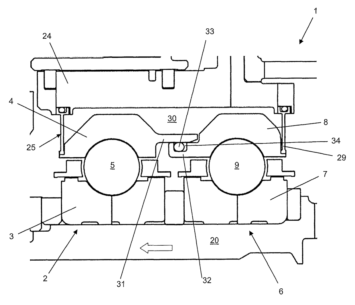
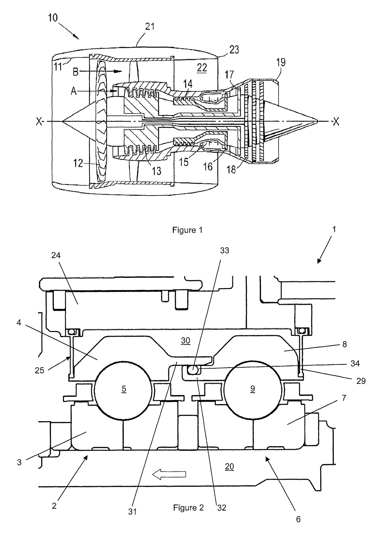
[0049]FIG. 2 shows a stacked bearing structure 1 comprising a first bearing 2 having a first inner race 3, a first outer race 4 and a first set of roller elements 5 housed between the first inner race 3 and the first outer race 5.

[0050]A second bearing 6 having a second inner race 7, a second outer race 8 and a second set of roller elements 9 housed between the second inner race 7 and the second outer race 8 is provided adjacent the first bearing 2.

[0051]Both of the inner races 3, 7 are connected to and rotate with a rotor shaft 20. Both of the outer races 4, 8 face an annular housing 24 which is a static component within the gas turbine engine.

[0052]The first bearing 2 further comprises a first compliant element which is a first flexible diaphragm 25 that is fixedly connected to the first outer race 4 at its radially inner end and slidably connected to the housing 24 at its radially outer end. The first flexible diaphragm 25 is provided at a first axial end of the stacked bearing s...

second embodiment

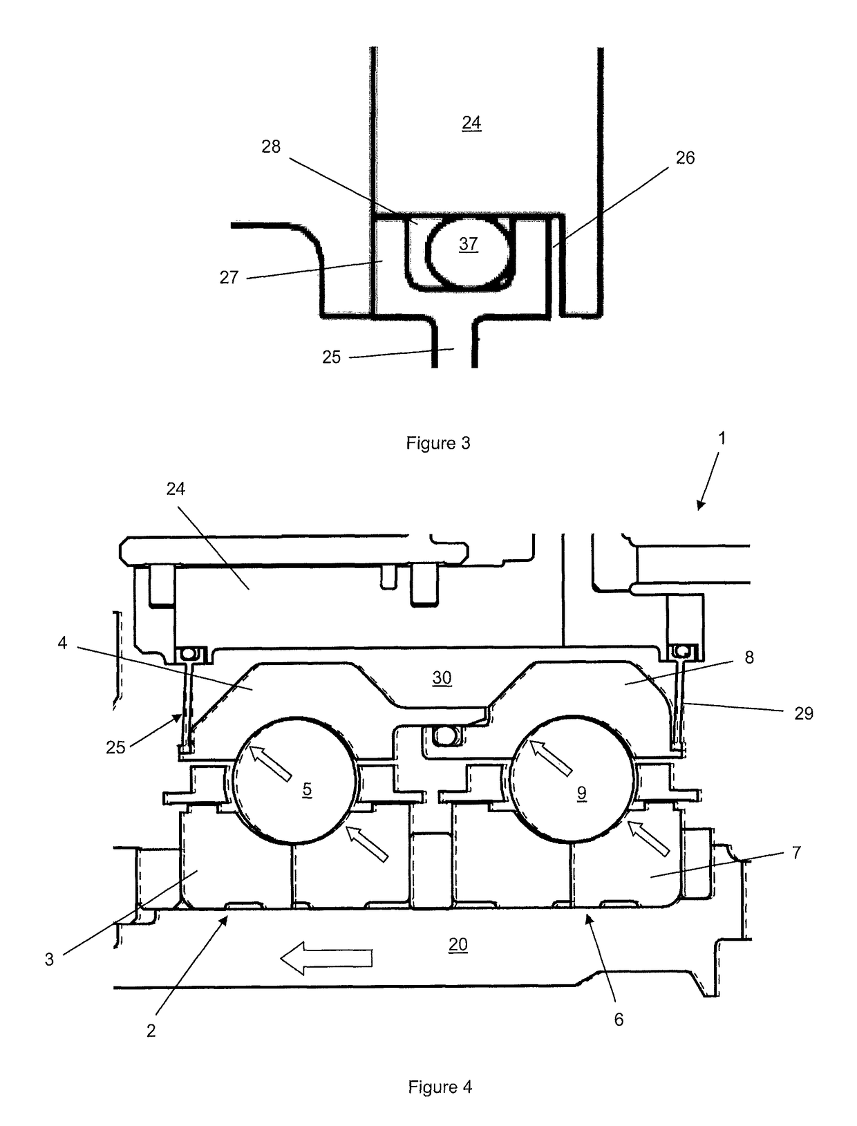
[0073]The second embodiment differs from the first in that the first flexible diaphragm 25, first outer race 4 and housing 24 define a first pressure chamber 30A and the second flexible diaphragm 29, second outer race 8 and housing 24 define a second pressure chamber 30B.

[0074]The first flexible diaphragm 25 is proximal the second bearing 6 (towards the axial middle of the stacked bearing structure 1) and the second flexible diaphragm is distal the first bearing 2 (at an axial end of the stacked bearing structure 1). The first and second flexible diaphragms 25, 29 are slidably mounted to the housing in the manner shown in FIG. 3.

[0075]The outer races 4, 8 are slidably mounted to the housing 24. The housing 24 comprises a first radial extension 34 against which the first outer race 4 is slidably mounted. The housing 24 further comprises a second radial extension 35 against which the second outer race 8 is slidably mounted. Each radial extension has an annular projection 36, against w...


PUM


Abstract

Load sharing stacked bearing structure including first bearing having a first inner race, first outer race and first set of roller elements housed between first inner race and first outer race and a second bearing having a second inner race, second outer race and second set of roller elements housed between second inner race and the second outer race. A housing surrounds the first and second bearings. First compliant element is provided with the first compliant element connected between the housing and the first outer race. The first compliant element, first outer race and housing define at a pressure chamber. The first outer race axially slidable relative to the second outer race such that an increase in pressure in pressure chamber causes a change in axial spacing between the outer races. This induces an additional axial load on the bearings which helps balance thrust load sharing.

Description

TECHNOLOGICAL FIELD[0001]The present disclosure relates to a bearing arrangement and a gas turbine engine having such a bearing arrangement.BACKGROUND[0002]In gas turbine engines, one or more rotors of the engine can be subjected to axial thrust loads during operation. Thrust loads arise in a gas turbine engine as the result of pressure imbalances. For example, a compressor has a higher downstream pressure than upstream pressure which forces the compressor upstream (towards the intake) whereas a turbine has a higher upstream pressure than downstream pressure which forces the turbine downstream (towards the exhaust nozzle). The thrust loads urging the compressor upstream and the compressor downstream are high and uncertain.[0003]The thrust loads are often at their maximum during the periods of highest power output for the engine. In a gas turbine engine providing jet propulsion for an aircraft, this period of maximized power output can occur when the aircraft is taking-off and / or cli...

Claims


Application Information

Patent Timeline
Patent Type & Authority Patents(United States)
IPC IPC(8): F16C27/00F16C33/78F16C25/08F02C7/06F16C41/02F01D25/16F16C19/06F16C19/52F16C19/54F16C35/04F16C19/16
CPCF16C19/54F01D25/164F02C7/06F16C19/06F16C19/522F16C25/08F16C33/7823F16C35/042F16C41/02F01D25/16F16C2360/23F05D2220/32F05D2240/54F05D2260/15F16C19/16F16C19/542
Inventor GALLIMORE, STEPHENFLETCHER, PAULPETERS, PHILIP
Owner ROLLS ROYCE PLC
Why Eureka
Try Eureka