
Seamless end connection for conveyor belts

a conveyor belt and end connection technology, applied in the direction of transportation and packaging, mechanical equipment, other domestic objects, etc., can solve the problems of inability to splice or attach single fabric belts, difficulty in spicing and forming end connections without mechanical fasteners, and inability to assemble connectors

Active Publication Date: 2017-11-28
UNIBAND USA LLC
View PDF14 Cites 24 Cited by
  • Summary
  • Abstract
  • Description
  • Claims
  • Application Information

AI Technical Summary

Benefits of technology

The solution provides a secure, seamless end connection that withstands high tensile loads and maintains a continuous surface, suitable for sanitary environments, with improved bonding strength and reduced risk of corrosion or particle accumulation.

Problems solved by technology

However, there are fewer ways to splice or attach single fabric belts in a manner that meets load and tension requirements, while allowing the belt to be used in a sanitary environment or other application that preferably utilizes a belt with a seamless or continuous upper surface.
Other conveyor belts, such as those with multiple fabric layers and thermosetting cover materials, can also experience similar difficulties in spicing and forming end connections without the use of mechanical fasteners.
Although mechanical fasteners can provide a secure connection capable of undergoing high tensile loads, these connectors can be undesirable in sanitary processing environments, such as food preparation, and other similar environments, due to the potential for corrosion and accumulation of particles at the connector, among other commonly understood drawbacks.
This form of connection can be difficult and time consuming to form properly, and typically requires the opposing wedges to be consistently formed across the width of the belt at an angle that is small enough to provide sufficient surface area for consistent bonding strength that meets the requisite tensional forces for using the belt.
Commonly, these opposing skived wedges can be uneven and result in inconsistent belt thicknesses at the overlapping connection area, an unstable overall connection, and an increased potential for the belt to wonder on a conveyor system.

Method used


Image

  • Seamless end connection for conveyor belts
  • Seamless end connection for conveyor belts
  • Seamless end connection for conveyor belts

Examples


Embodiment Construction

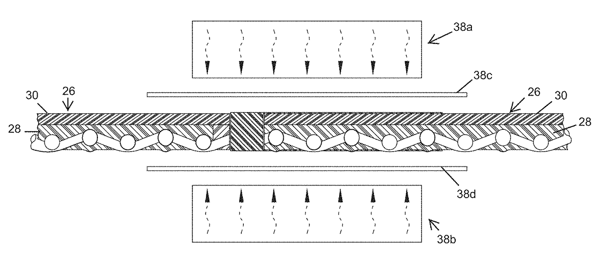
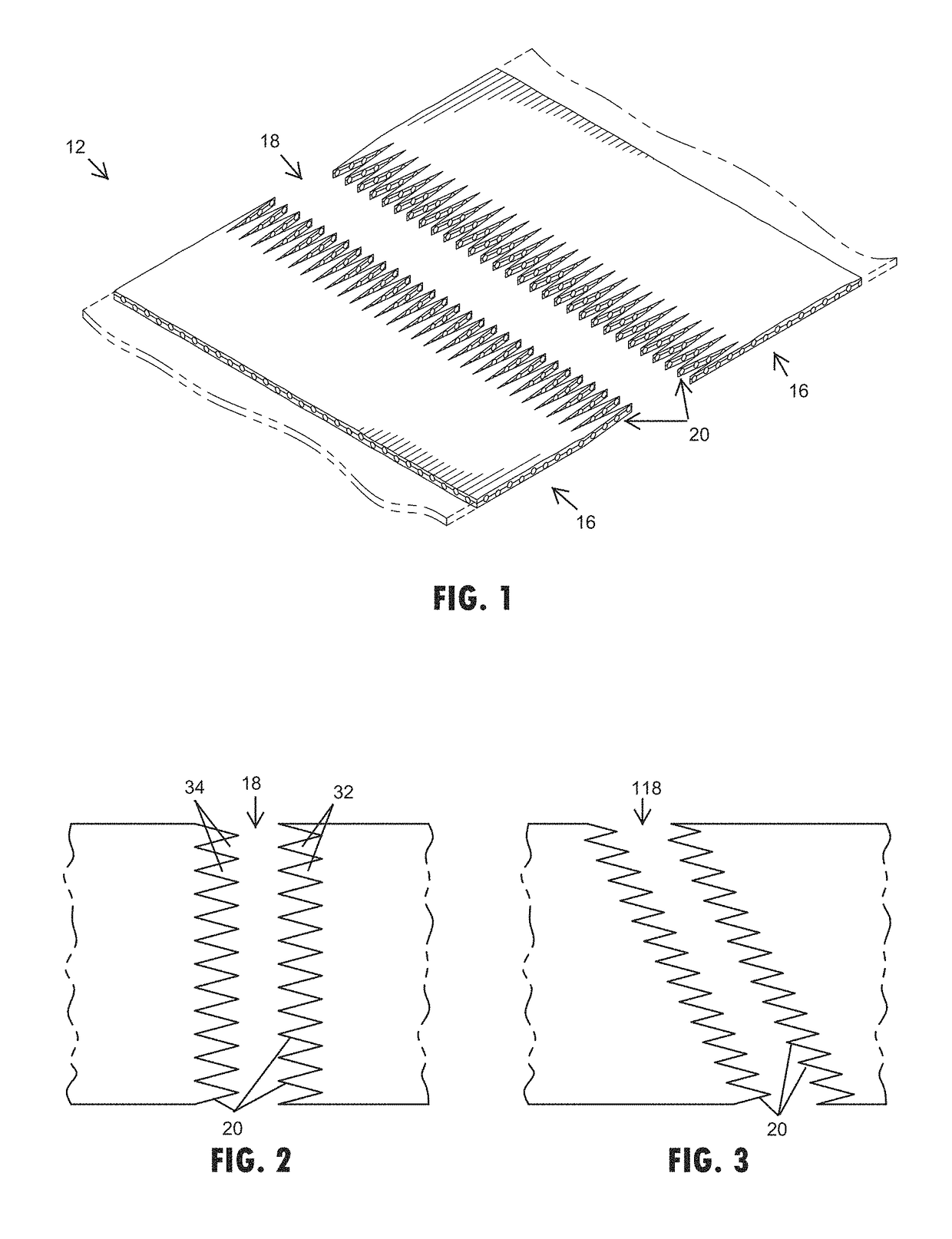
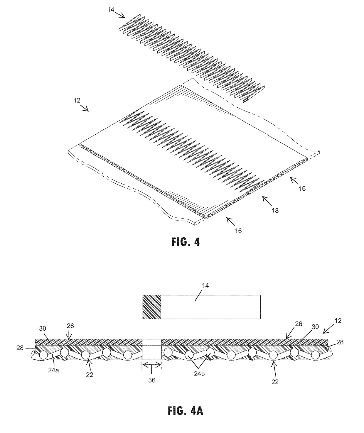
[0037]Referring now to the drawings and the illustrative embodiments depicted therein, an end connection 10 for a conveyor belt 12 can be formed in accordance with the present invention to form an endless loop or otherwise attach the conveyor belt to another section of belting. The end connection 10 for the conveyor belt 12 generally includes a thermoplastic connector 14 or joining material, such as a thermoplastic copolyester elastomer or like material that thermally engages between the opposing end portions 16 of the conveyor belt 12. The end portions 16 of the belting may include a splice formation or configuration, such as a finger splice formation 18, 118, 218 (FIGS. 1-12B) or a step formation 318 (FIGS. 13A-C) or the like. The finger splice formation 18 is cut or formed to provide cut edges 20 that may be generally perpendicular to an upper surface of the conveyor belt 12 and expose the fabric carcass 22 of the conveyor belt 12. Upon heating the end portions 16 to thermally en...


PUM

PropertyMeasurementUnit
melting pointsaaaaaaaaaa

Abstract

An endless conveyor belt loop includes a conveyor belt that has an elongated body and a substantially uniform width. The ends of the conveyor belt each include a splice formation extending across the width of the conveyor belt that are each configured to mate with the other. A thermoplastic connector is thermally engaged between exposed surfaces formed by the splice formation at the ends of the conveyor belt. When the splice formations are aligned, the thermoplastic connector is thermally engaged and continuously interconnected between the ends for conveyor belt to form a seamless end connection. The thermoplastic connector comprises a thermoplastic copolyester elastomer.

Description

CROSS REFERENCE TO RELATED APPLICATION[0001]The present application claims the benefit of U.S. provisional application Ser. No. 62 / 278,511, filed Jan. 14, 2016, which is hereby incorporated herein by reference in its entirety.FIELD OF THE INVENTION[0002]The present invention relates generally to conveyor belt end connections and methods of attachment, and more particularly to spliced end connections of conveyor belts.BACKGROUND OF THE INVENTION[0003]There are several known ways to splice or attach the ends of a conveyor belt together that can be used based on the types of material and thickness of the belting, in addition to the anticipated loads and tension that the belt will experience in use. However, there are fewer ways to splice or attach single fabric belts in a manner that meets load and tension requirements, while allowing the belt to be used in a sanitary environment or other application that preferably utilizes a belt with a seamless or continuous upper surface. Other con...

Claims


Application Information

Patent Timeline
Patent Type & Authority Patents(United States)
IPC IPC(8): B65G15/34B29C65/54B29D29/06F16G3/10B29C65/00B29K67/00B29K105/00B29K105/08B29L9/00B29L31/00
CPCF16G3/10B29C65/54B29C66/431B29C66/71B29C66/721B29C66/729B65G15/34B29D29/06B29L2031/7092B29K2067/00B29K2105/0809B29K2105/256B29L2009/00B29C65/18B29C65/4815B29C65/5057B29C65/5071B29C65/56B29C65/8253B29C66/0044B29C66/1142B29C66/1282B29C66/12841B29C66/14B29C66/223B29C66/2274B29C66/4322B29C66/4324B29C66/7212B29C66/72141B29C66/723B29C66/7292B29C66/73921B29C66/73941B29C66/83221B29C66/91411B29C66/9192B29K2267/00B29K2277/00B29K2201/00B29K2311/10B29K2027/06B29K2021/003B29K2075/00
Inventor MARCHETTI, FRANCO MILCO
Owner UNIBAND USA LLC
Learn More