Sky luminance mapping system and mapping method

a luminance mapping and luminance technology, applied in the field of sky luminance mapping technique, can solve the problems of affecting the actual background environment of observers, the inability of conventional hdri technology to apply under direct sun light exposure for a long time, and the overheating of the photo sensor in the camera, etc., and achieve the effect of high dynamic range imaging

Active Publication Date: 2017-11-28
NAT TAIWAN UNIV OF SCI & TECH
View PDF4 Cites 0 Cited by
  • Summary
  • Abstract
  • Description
  • Claims
  • Application Information

AI Technical Summary

Problems solved by technology

The luminance of the sun is much greater than the background luminance of the environment, and thus the direct sun light may hinder the observers from observing the actual background environment around the sun.
In most cases, the conventional HDRi technology cannot be applied under direct sun light exposure for a long time.
Specifically, the luminance of the direct sun light as a point light source often exceeds the total background luminance, and the direct sun light may overheat the photo sensor in the camera while the exposure level is adjusted according to the background luminance.
In another aspect, the reliance of a filter for reducing the luminance of the direct sun light entering the photo sensor may lead to the interference of baseband noises with other signals and the resultant distortion of the signals.
Besides, the filter need be manually replaced, which results in significant costs and time and reducing the expecting advantage of fast mapping.

Method used


Image

  • Sky luminance mapping system and mapping method
  • Sky luminance mapping system and mapping method
  • Sky luminance mapping system and mapping method

Examples


Embodiment Construction

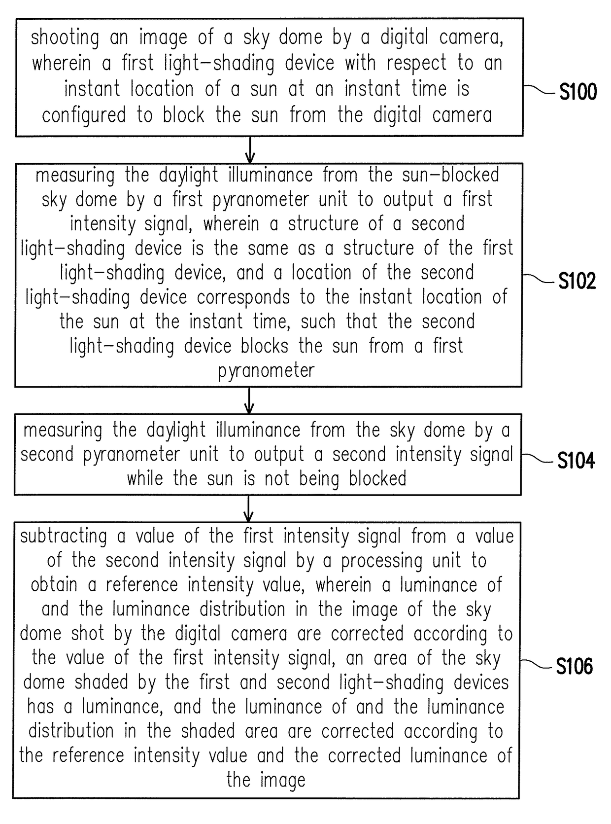
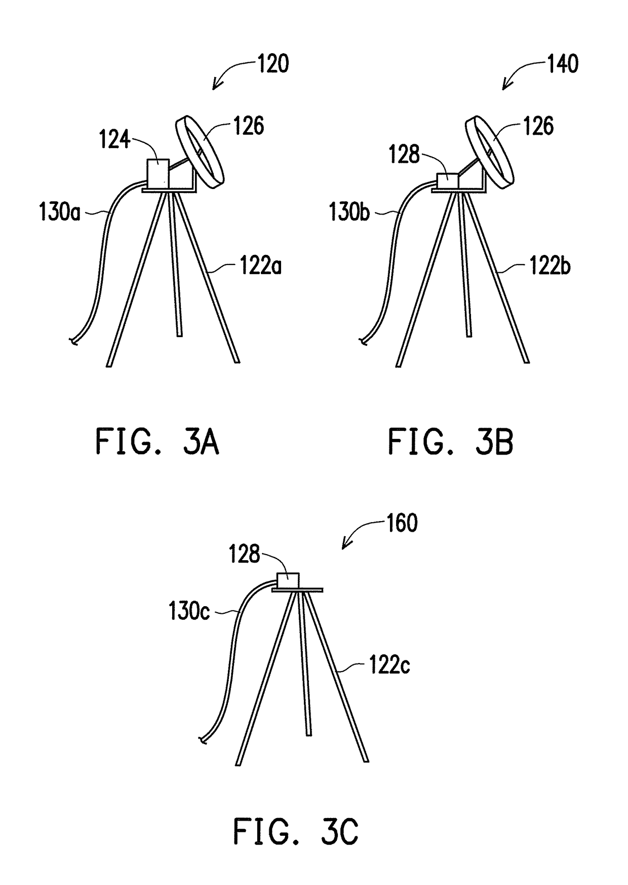
[0022]In an embodiment of the invention, a sky luminance mapping system and a sky luminance mapping method are provided. Specifically, through the overall arrangement of pyranometers and light-shading devices (e.g., light-shading rings or light-shading sheets), sun light and sky light can be respectively measured. During the measurement, components in the sky luminance mapping system are not replaced manually because of the HDRi technology, and thereby both cost and labor can be saved. Experimental tests have been run on the system and the method provided herein, and the influence of direct sunlight has been carefully avoided in all experiments. In addition, the system can provide fast updating rate of the exterior luminous environment and can be operated outdoor continuously for several hours.

[0023]According to an embodiment of the invention, the sky light can be timely detected, such that the sky light information can be instantly provided while particular attention is given to th...


PUM


Abstract

A sky luminance mapping system includes a camera unit, two pyranometer units and a processing unit. Camera unit includes a fisheye lens to shoot image of sky dome and is equipped with light-shading devices which block the sun from the camera unit corresponding to instant location of the sun at instant time. First pyranometer unit measures daylight illuminance from the sky dome and outputs first intensity signal while the light-shading device is applied to block the sun. Second pyranometer unit measures daylight illuminance from the sky dome and outputs second intensity signal without blocking the sun. A reference intensity value is obtained by subtracting a value of the first intensity signal from a value of the second intensity signal. According to the value of the first intensity signal and the reference intensity value, a total luminance of and the luminance distribution in the image of the sky dome are corrected.

Description

CROSS-REFERENCE TO RELATED APPLICATION[0001]This application claims the priority benefit of Taiwan application serial no. 104107462, filed on Mar. 9, 2015. The entirety of the above-mentioned patent application is hereby incorporated by reference herein and made a part of this specification.FIELD OF THE INVENTION[0002]The invention relates to a sky luminance mapping technique that can be applied to instantly shoot an image of a sky dome in the daylight.DESCRIPTION OF RELATED ART[0003]Observation of images of the sky dome is sometimes deemed necessary. For instance, in case of weather observation, clouds in the sky need be monitored for a long period of time. However, the sun shows up in the daylight sky. The luminance of the sun is much greater than the background luminance of the environment, and thus the direct sun light may hinder the observers from observing the actual background environment around the sun.[0004]According to the related art, several photo-shooting techniques may...

Claims


Application Information

Patent Timeline
Patent Type & Authority Patents(United States)
IPC IPC(8): H04N7/00G01J1/42G01J1/04G01J1/02
CPCG01J1/4214G01J1/0242G01J1/0437G01J1/0418G01J2001/4266
Inventor CHIOU, YUN-SHANG
Owner NAT TAIWAN UNIV OF SCI & TECH
Why Eureka
Try Eureka