Device and method for inspecting inside of underground pipe line and method of inspecting concrete on inside of underground pipe line for deterioration

a technology of underground pipe and inspection method, which is applied in the direction of instruments, flaw detection using microwaves, and reradiation, etc., can solve the problems of insufficient search conducted only upward of the underground pipe, insufficient caving of roads, and environmental problems, and achieve accurate measurement

Inactive Publication Date: 2006-11-07
BURN AM
View PDF16 Cites 34 Cited by
  • Summary
  • Abstract
  • Description
  • Claims
  • Application Information

AI Technical Summary

Benefits of technology

[0010]Here, the two-dimensional radar image is a diagram plotted by analyzing the radar signal, where the traveling direction of the pipe line internal self-propelled vehicle, that is, the distance in the axial direction of the underground pipe, serves as an abscissa and the distance outward of the inner peripheral surface of the underground pipe line serves as an ordinate. With the third device for inspecting the inside of an underground pipe line, it is possible to create two-dimensional radar images in a plurality of directions outward of the inner peripheral surface of the underground pipe, that is, in a plurality of directions perpendicular to the traveling direction of the pipe line internal self-propelled vehicle. Further, because the pipe line internal self-propelled vehicle is provided with the antenna position detection means for detecting the position of the antenna, the actual search direction in searching for cavities in the ground around the underground pipe can be accurately associated with a two-dimensional radar image obtained by analyzing the radar signals and the search for cavities can be conducted with good accuracy.
[0012]As the fifth device for inspecting the inside of an underground pipe line, in the above-described device for inspecting the inside of an underground pipe line, respective linkages of the parallel link mechanism can have a variable length and can be extended or contracted, and the upper surface of the antenna can be tilted forward and backward so as to follow the shape of the ceiling. With the fifth device for inspecting the inside of an underground pipe line, the upper surface of the antenna can follow the ceiling shape and the accuracy of inspection can be improved.
[0013]As the sixth device for inspecting the inside of an underground pipe line, in the above-described device for inspecting the inside of an underground pipe line, the pipe line internal self-propelled vehicle may comprise a fisheye lens camera for taking the pictures of the inner peripheral surface of the underground pipe line in front of the vehicle in the traveling direction and the expanded image may be created and displayed in a real time mode by the on-ground control unit from the images picked up with the fisheye lens camera. Here, the expanded image is a detailed plane image of the inner peripheral surface of the underground pipe created by converting the images of the inner peripheral surface of the underground pipe line that were picked up with the fisheye lens camera, where the traveling direction of the pipe line internal self-propelled vehicle, that is, the distance in the axial direction of the underground pipe, serves as an abscissa and the distance outward of the inner peripheral surface of the underground pipe line serves as an ordinate. With the sixth device for inspecting the inside of an underground pipe line, there is fixedly provided a fisheye lens camera for taking pictures of the inner peripheral surface of the underground pipe line and an expanded image is created from the images picked up with the fisheye lens camera. Therefore, the detailed expanded image of the inner peripheral surface of the underground pipe can be obtained and cracks or fractures of the underground pipe can be detected without using a complex mechanism for rotating the camera.
[0016]As the ninth device for inspecting the inside of an underground pipe line, in the above-described device for inspecting the inside of an underground pipe line, the pipe line internal self-propelled vehicle may comprise an infrared encoder for measuring the travel distance thereof. With the ninth device for inspecting the inside of an underground pipe line, the distance from the inspection start point of the underground pipe line to the inspection position can be accurately measured and the positions where the cavities or deformations, cracks, and fractures of the underground pipe are present can be reliably determined from the distance from the inspection start point to the position where the cavities or deformations, cracks, and fractures of the underground pipe are present by establishing the correspondence between this distance and each of the above-described image.
[0026]As the seventeenth device for inspecting the inside of an underground pipe line, in the above-described device for inspecting the inside of an underground pipe line, supporters providing for smooth contact between the inspection unit and the inner peripheral surface when the inspection unit moves forward or backward or rotated about the axis thereof are provided on the outer peripheral surface of the inspection unit.

Problems solved by technology

Underground pipes that are buried in the ground and used for sewers and the like can cause environmental problems such as caving of roads or leakage of sewage due to cavities in the ground surrounding the underground pipe that occurred when the pipe was buried and cracks or fractures in the underground pipe that appeared thereafter.
However, a search conducted only upward of the underground pipe is insufficient for preventing caving of roads, and a search toward both sides and downward of the underground pipe is also necessary.
However, when the camera is fixed, a detailed image is difficult to obtain, and rotating the camera requires a complex mechanism.
Further, devices designed to display cracks or pattern of irregularities on the inner peripheral surface of a pipe line with a three-dimensional convergence image have not been found.
In concrete underground sewers, hydrogen sulfide contained in sewage is converted into sulfuric acid by sulfur oxidizing bacteria, and this sulfuric acid reacts with cement components contained in the concrete and is converted into gypsum dehydrate, thereby causing concrete embrittlement.
The embrittled portions have to be removed, for which purpose the concrete of the inner peripheral surface of the sewer has to be sampled and analyzed, this operation being costly and troublesome.
Moreover, the analysis requires about 10 days.
Further, because the cavity inspection device using a pipe line internal self-propelled vehicle has a large size, inspection of underground pipes of small diameter, such as lateral sewers connected from the ground surface to the main sewer pipe, is difficult to conduct by employing such a large cavity inspection devices using a pipe line internal self-propelled vehicle.

Method used


Image

  • Device and method for inspecting inside of underground pipe line and method of inspecting concrete on inside of underground pipe line for deterioration
  • Device and method for inspecting inside of underground pipe line and method of inspecting concrete on inside of underground pipe line for deterioration
  • Device and method for inspecting inside of underground pipe line and method of inspecting concrete on inside of underground pipe line for deterioration

Examples


first embodiment

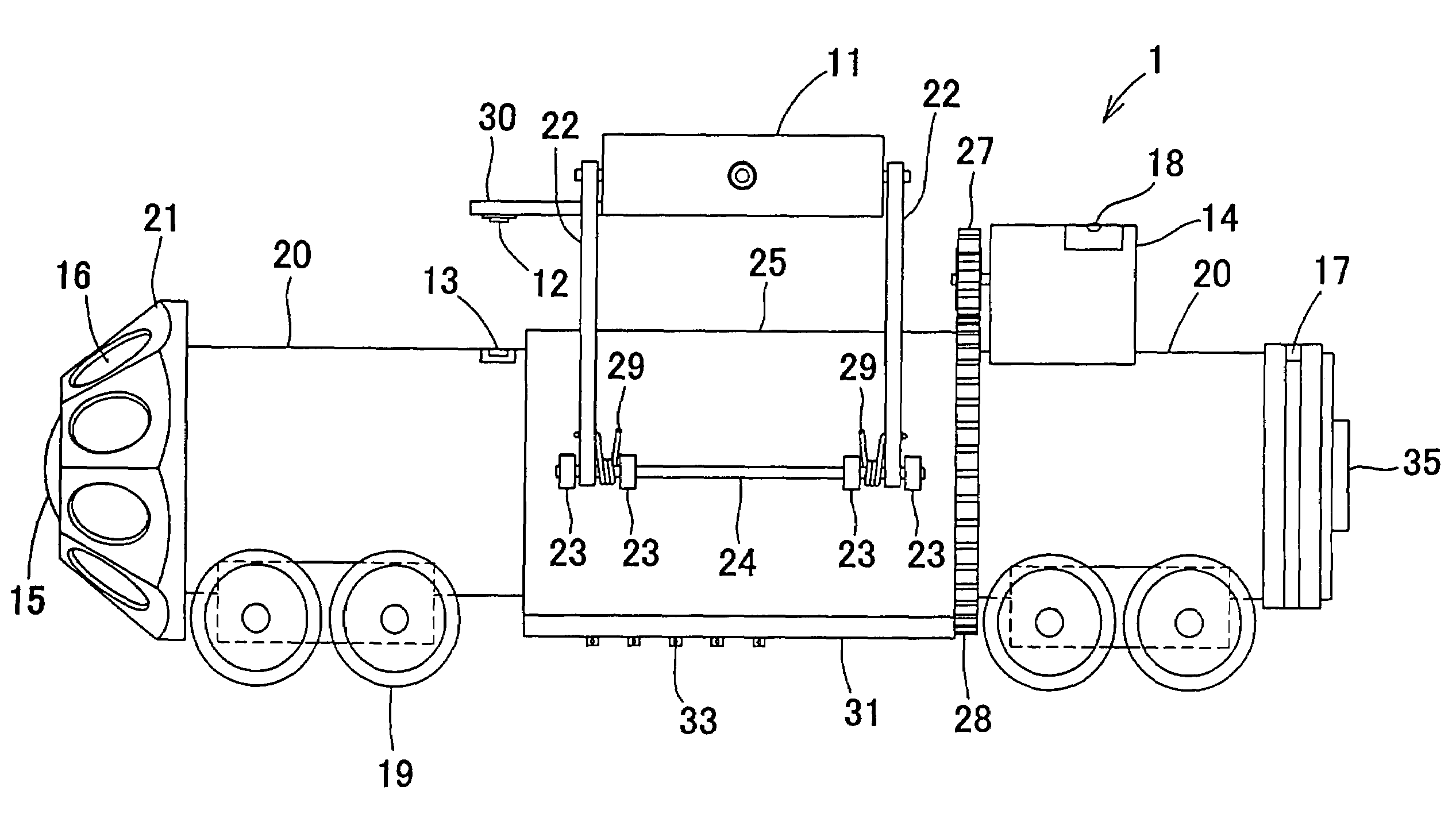
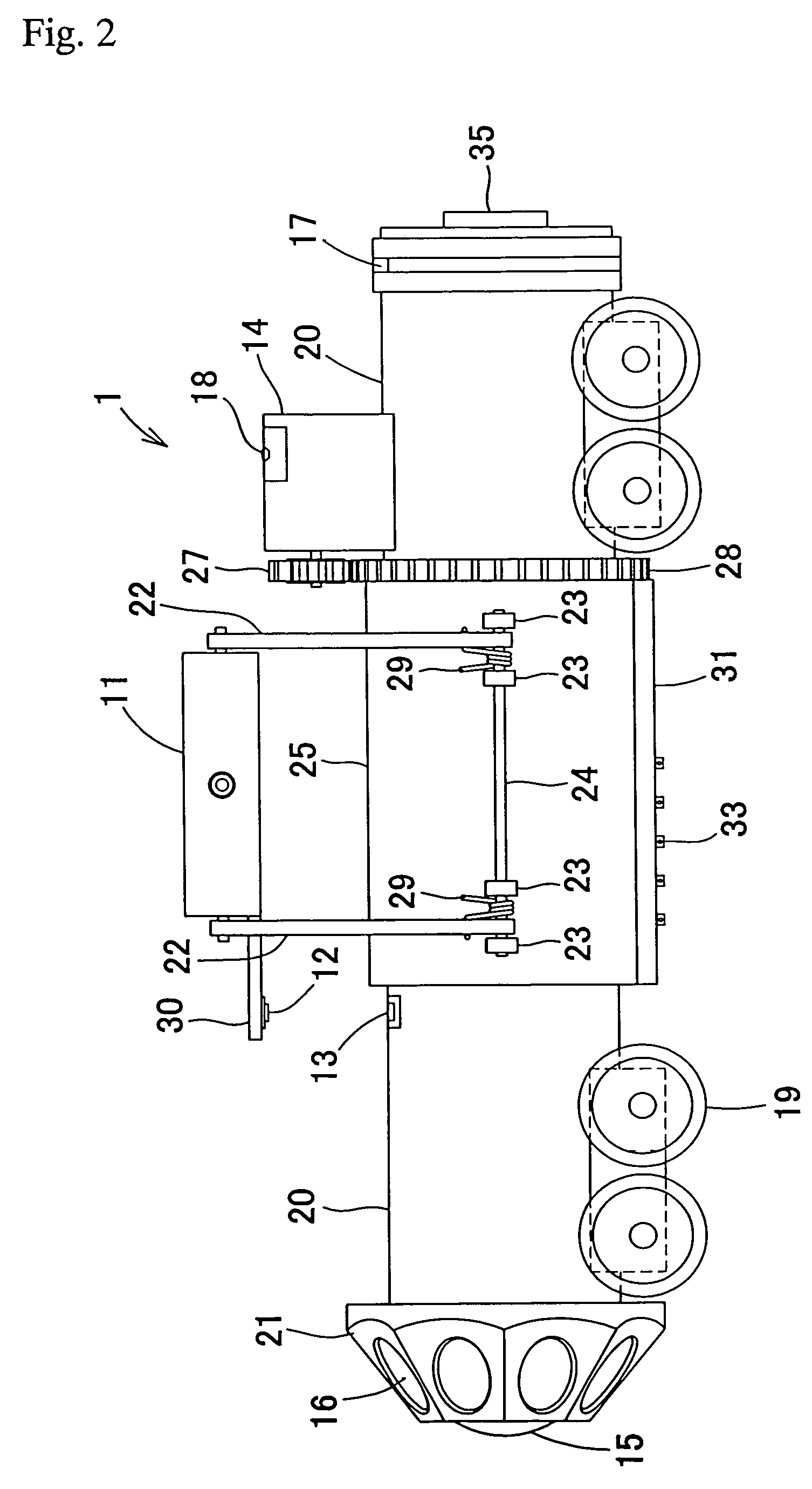
[0063]Further, the signal outputted from the rotating radar antenna 11 has to be transmitted to the on-ground control unit 2. Here, a slip ring is provided on the surface of the inner sleeve 26, and a brush 33 made from carbon is fit into a brush fitting orifice 32 of the brush mounting portion 31 provided at the outer sleeve 25, so that the brush is brought into contact with the slip ring. A wire for the signal outputted from the radar antenna 11 is connected to the brush 33. Further, the signal wire which is conductively linked to the slip ring on the surface of the inner sleeve 26 is connected to the on-ground control unit 2 via a connector 35 for a connecting cable. In the first embodiment, the above-described mechanism is used to pick up the signals outputted from the rotating radar antenna 11.

[0064]The control unit 2 receives and analyzes the signals outputted from the rotating radar antenna 11, forms a two-dimensional radar image with a traveling direction of the pipe line in...

second embodiment

[0074]With the above-described underground pipe line internal inspection device of the second embodiment, a concrete deterioration diagnostic reagent which changes the color of the surface to which it has adhered according to the presence or absence of concrete deterioration is sprayed on the inner peripheral surface of concrete in the underground pipe line and the results are picked up with a fisheye lens camera. Therefore, a decision relating to the presence or absence of concrete deterioration in the line can be made based on the picked-up images.

[0075]Further, the above-described underground pipe line internal inspection device of the second embodiment, similarly to the underground pipe line internal inspection device of the first embodiment, has a radar for cavity inspection, a gyro, a laser sensor, and a function of establishing the correspondence between the radar image and the expanded image, or an infrared encoder. Therefore, it demonstrates functions and effects identical ...

third embodiment

[0077]In FIGS. 9 to 12, the parallel link mechanism 60 for raising and lowering the antenna in the pipe line internal self-propelled vehicle 59 of the device for inspecting the inside of an underground pipe line of the third embodiment has the following structure.

[0078]A rectangular antenna support frame 62 is so disposed that the short side thereof is aligned in the front-back direction along the traveling direction of the pipe line internal self-propelled vehicle 59 and comprises four guide bars 63 extended with downward inclination forward or backward at the front end or rear end of the long side of the antenna support frame 62. The inner side surfaces of the long sides of the antenna support frame 62 and guide bars 63 are inclined so as to open with upward and outward inclination with respect to the traveling direction of the pipe line internal self-propelled vehicle 59. Further, guide rollers 65 are rotatably mounted on the outer side surfaces of the long sides of the antenna s...


PUM

PropertyMeasurementUnit
diameteraaaaaaaaaa
travel distanceaaaaaaaaaa
coloraaaaaaaaaa

Abstract

A device for inspecting the inside of an underground pipe line which makes it possible to search for cavities on the outside of the underground pipe over the entire internal peripheral surface of the underground pipe, that is, not only upward of the underground pipe, but also toward both sides and downward thereof, to obtain detailed images of the inner peripheral surface of the pipe line without using a complex mechanism, and to display patterns of cracks and irregularities on the inner peripheral surface of the underground pipe by three-dimensional convergence images. The device comprises a pipe line internal self-propelled vehicle and an on-ground control unit, and the pipe line internal self-propelled vehicle is provided with a radar antenna, a camera equipped with a fisheye lens, a gyro, a laser sensor, and an infrared encoder.

Description

TECHNICAL FIELD[0001]The present invention relates to a device for inspecting the inside of an underground pipe line in an underground pipe embedded in the ground, inspection method therefor, and a method for inspecting concrete deterioration inside an underground pipe line of an underground pipe made from concrete.BACKGROUND ART[0002]Underground pipes that are buried in the ground and used for sewers and the like can cause environmental problems such as caving of roads or leakage of sewage due to cavities in the ground surrounding the underground pipe that occurred when the pipe was buried and cracks or fractures in the underground pipe that appeared thereafter. The state of the underground pipe lines has to be inspected to prevent such problems effectively. Devices designed to be employed for such an inspection have been suggested and used. A cavity inspection device using a pipe line internal self-propelled vehicle that is equipped with a radar is described in Japanese Patent App...

Claims


Application Information

Patent Timeline
Patent Type & Authority Patents(United States)
IPC IPC(8): G01M19/00G01M99/00F16L55/28F16L55/32G01N22/02G01S17/88
CPCF16L55/28F16L55/32G01N22/02G01S17/88F16L2101/30B08B9/02
Inventor TARUMI, MINORU
Owner BURN AM
Why Eureka
Try Eureka