High efficiency polarized ULF/VLF/RF transciever antenna

a transciever antenna, high-efficiency technology, applied in the direction of polarised antenna unit combinations, basic electric elements, antennas, etc., can solve the problems of limiting the ability to control the polarization and directionality of such arrays, limiting the ability to achieve multiple polarization transmission with a broad frequency range from the same small antenna, and inefficient transceiver antennas for transmitting signals significantly larger than radiation wavelengths.

Active Publication Date: 2017-11-28
RAYTHEON CO
View PDF15 Cites 0 Cited by
  • Summary
  • Abstract
  • Description
  • Claims
  • Application Information

AI Technical Summary

Benefits of technology

[0004]The present invention provides a transmission antenna having a closed-loop core and two electrically-conductive windings arranged on the closed-loop core. The windings are each capable of producing a magnetic flux along the closed-loop core in opposing directions for generating a magnetic field. The transmission antenna may generate a polarized signal having a relatively flat frequency response, and may provide broadband transmission of the polarized signal across a distance. The transmission antenna may be electrically-small and have a high-efficiency that is nearly independent of the transmission frequency. The magnetic field generated by the transmission antenna may be strongly polarized within the plane of the closed-loop core, and the polarized signal may be strongly polarized within the same plane. Multiple polarized signals may be provided by employing additional windings, which may be independently and continuously controlled. A phase-shifted electrical signal applied to the windings may vary the directionality of the transmitted polarized signal within the plane of the closed-loop core. The effective cross-talk between the respective windings may be minimal, and additional windings for receiving a signal may simultaneously be used on the closed-loop core. The polarization of the receiver antenna may be similarly controlled by a phase delay of constituent receiver windings. The strongly polarized signal generated by the transmission antenna may also be used for such applications as ground penetrating radar, misaligned-beam radar, and more.
[0006]Embodiments of the invention may include one or more of the following additional features. That is, the first winding and the second winding may be arranged on the closed-loop core in magnetic symmetry, such that magnetic field leakage through the sides of the closed-loop core is reduced and polarization of the magnetic field within the plane of the closed-loop core is enhanced.
[0008]According to yet another embodiment of the invention, the respective windings may be configured to reduce electrical resistance and / or inductive impedance, such that electrical current flowing through the respective windings is increased for enabling an increase in the magnetic moment of the transmission antenna for enhancing the strength of the transmitted polarized signal. For example, inductive impedance may be reduced by reducing or limiting the number of turns in the winding; and resistance may be reduced by reducing or limiting the length of the electrically-conductive wire, increasing the cross-sectional area of the wire, and / or using a wire made from a low-resistivity material.
[0010]In another embodiment, the closed-loop core may be configured to increase magnetic flux density, such as by increasing the mass of the closed-loop core and / or providing a closed-loop core made from high-magnetic permeability material.

Problems solved by technology

Transceiver antennas for transmitting a signal with a wavelength significantly larger than the wavelength of radiation are inefficient and typically do not provide polarization discrimination.
Cross-talk between individual ferrite rods usually limits the ability to control polarization and directionality of such arrays.
Achieving multiple polarization transmission with a broad frequency range from the same small antenna, in which the transmission wavelength is much greater than the size of the antenna, has remained a difficulty in the art.

Method used


Image

  • High efficiency polarized ULF/VLF/RF transciever antenna
  • High efficiency polarized ULF/VLF/RF transciever antenna
  • High efficiency polarized ULF/VLF/RF transciever antenna

Examples


Embodiment Construction

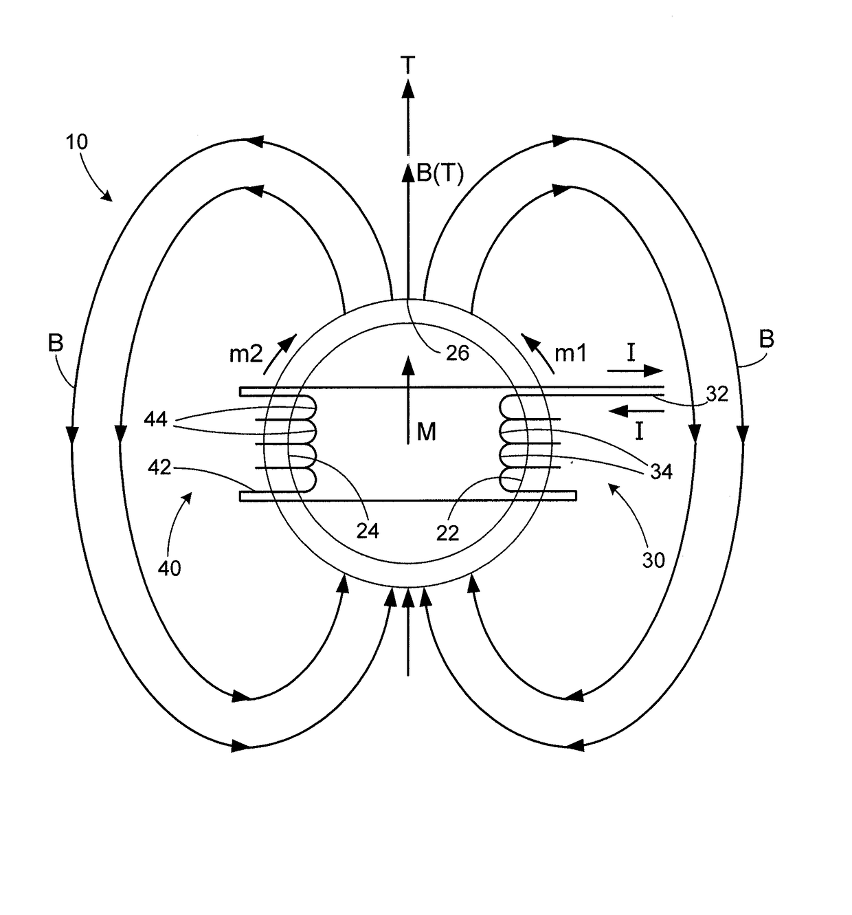
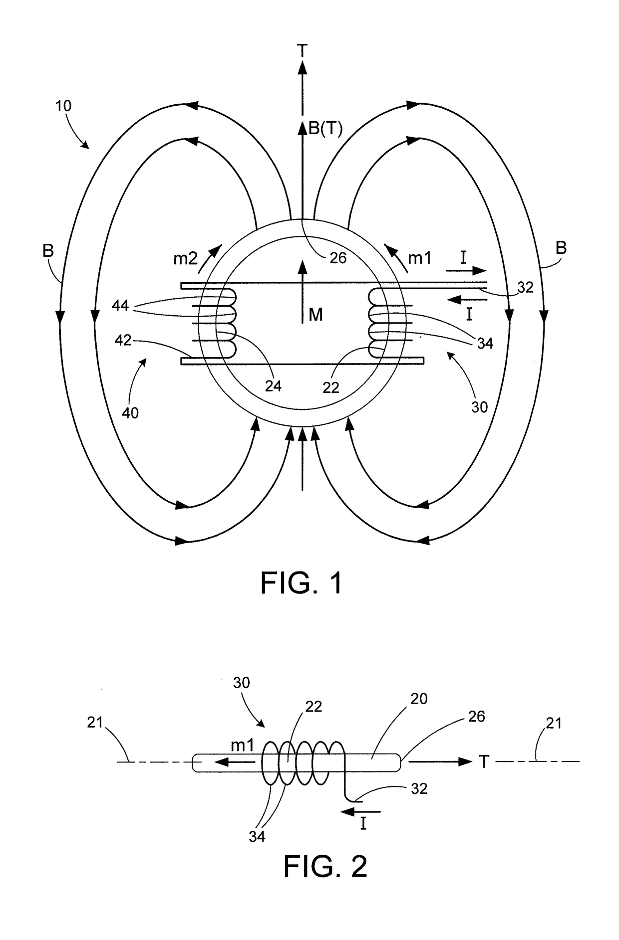
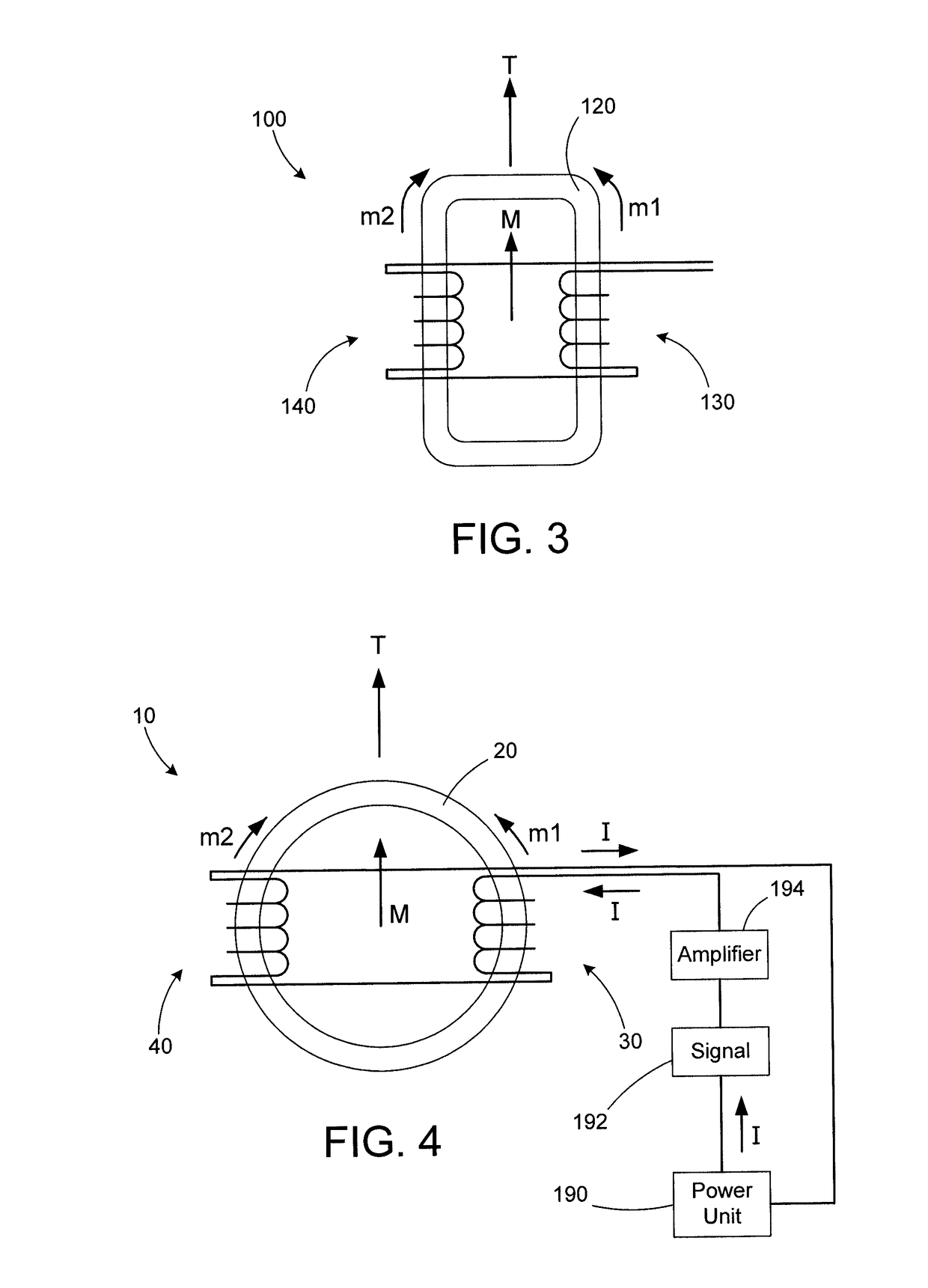
[0026]A transmission antenna includes a closed-loop core having at least two electrically-conductive windings arranged on the closed-loop core. The windings each generate a magnetic field when electrically actuated, and the windings each produce a magnetic flux along the closed-loop core in opposing directions. The transmission antenna may generate a polarized magnetic field within a plane of the closed-loop core and provide broadband transmission of a polarized signal having a relatively flat frequency response. The transmission antenna is electrically small, and the frequency of the polarized signal is nearly independent of the size of the closed-loop core. Multiple polarized signals may be provided, each being independently and continuously controlled through actuation of the windings. The direction of the polarized signal may also be varied within the plane of the closed-loop core through phase-modulation of the signal applied to each winding. Additional windings for transmittin...


PUM


Abstract

A transmission antenna includes a closed-loop core having at least two electrically-conductive windings arranged on the closed-loop core. The windings are each electrically-actuated to generate a magnetic flux along the closed-loop core in opposing directions. The transmission antenna may generate a polarized magnetic field within a plane of the closed-loop core and provide broadband transmission of a polarized signal having a relatively flat frequency response. The transmission antenna is electrically-small, and the frequency of the polarized signal is nearly independent of the size of the closed-loop core. Multiple polarized signals may be provided, each being independently and continuously controlled through actuation of the windings. The direction of the polarized signal may also be varied. Additional windings for receiving a signal may simultaneously be employed on the closed-loop core. A method for transmitting a polarized signal with the transmission antenna is also provided.

Description

RELATED APPLICATIONS[0001]This application claims the benefit of U.S. Provisional Application No. 61 / 929,248 filed Jan. 20, 2014, which is hereby incorporated herein by reference in its entirety.FIELD OF INVENTION[0002]The present invention relates generally to transmission antennas, and more particularly to high-efficiency polarized ULF / VLF / RF transceiver antennas having a closed-loop core.BACKGROUND[0003]Transceiver antennas for transmitting a signal with a wavelength significantly larger than the wavelength of radiation are inefficient and typically do not provide polarization discrimination. Ferrite rod arrays have been used at lower frequencies to increase the efficiencies of transceiver antennas. Cross-talk between individual ferrite rods usually limits the ability to control polarization and directionality of such arrays. The efficiency of the ferrite rod drops dramatically with a decrease of the length to diameter ratio of the ferrite rod and with the rod length to coil leng...

Claims


Application Information

Patent Timeline
Patent Type & Authority Patents(United States)
IPC IPC(8): H01Q7/08H04B5/00H01Q21/24H01Q3/34H01Q7/06H04B1/04
CPCH04B5/0093H01Q3/34H01Q7/06H04B5/0087H01Q21/245H04B1/0475H04B5/0081H01Q7/08
Inventor DOLGIN, BENJAMIN P.
Owner RAYTHEON CO
Why Eureka
Try Eureka