Eureka AIR delivers breakthrough ideas for toughest innovation challenges, trusted by R&D personnel around the world.

Printhead and an inkjet printer

a technology of inkjet printer and printhead, which is applied in the direction of printing and inking apparatus, etc., can solve the problem of limiting the rate at which data can be reliably transmitted

Active Publication Date: 2017-12-05
FUNAI ELECTRIC CO LTD
View PDF17 Cites 0 Cited by
  • Summary
  • Abstract
  • Description
  • Claims
  • Application Information

AI Technical Summary

Benefits of technology

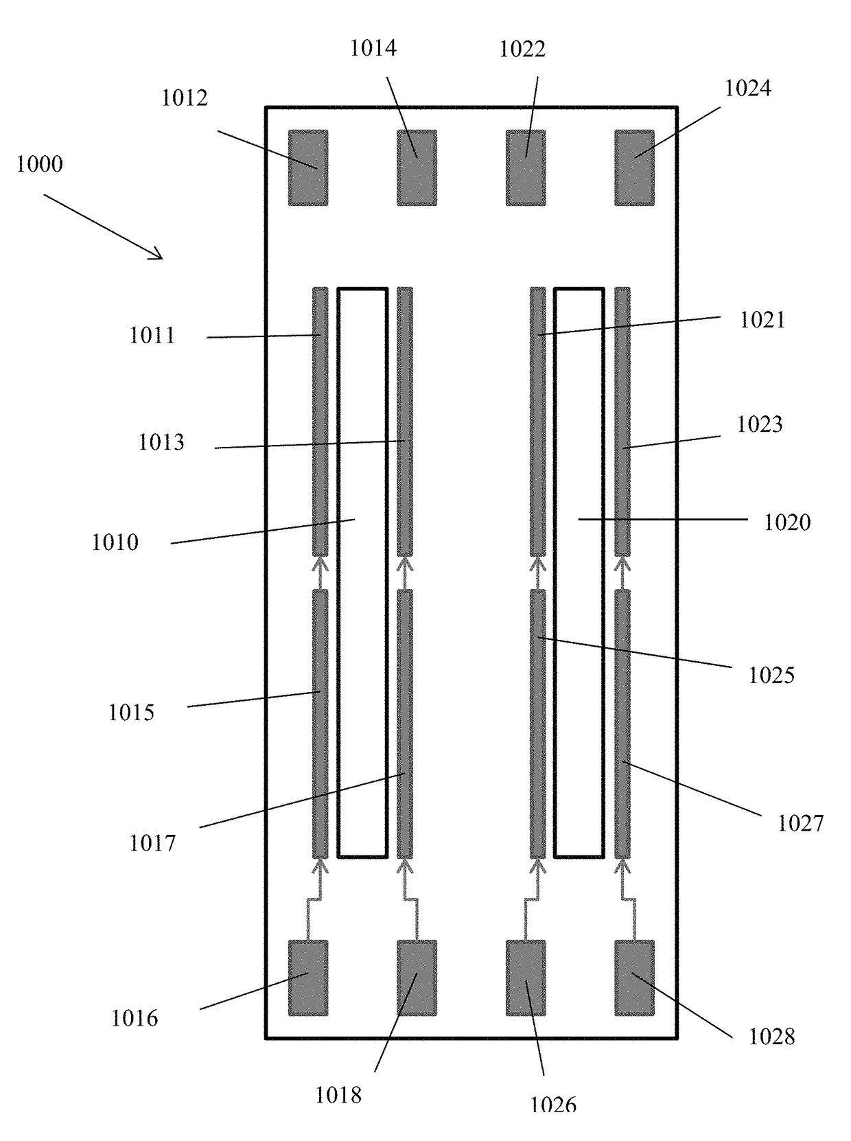
The present invention provides a printhead circuit and method that allow for a configurable combination of inputs and data rates. It also provides an inkjet heater chip architecture where the clock speed and number of I / O pads are user selectable. This allows for a single design to fit the needs of multiple applications and markets.

Problems solved by technology

The resistive and capacitive nature of the ribbon cable itself limits the rate at which data can be reliably transmitted.

Method used


Image

  • Printhead and an inkjet printer
  • Printhead and an inkjet printer
  • Printhead and an inkjet printer

Examples


Embodiment Construction

[0019]The headings used herein are for organizational purposes only and are not meant to be used to limit the scope of the description or the claims. As used throughout this application, the words “may” and “can” are used in a permissive sense (i.e., meaning having the potential to), rather than the mandatory sense (i.e., meaning must). Similarly, the words “include,”“including,” and “includes” mean including but not limited to. To facilitate understanding, like reference numerals have been used, where possible, to designate like elements common to the figures.

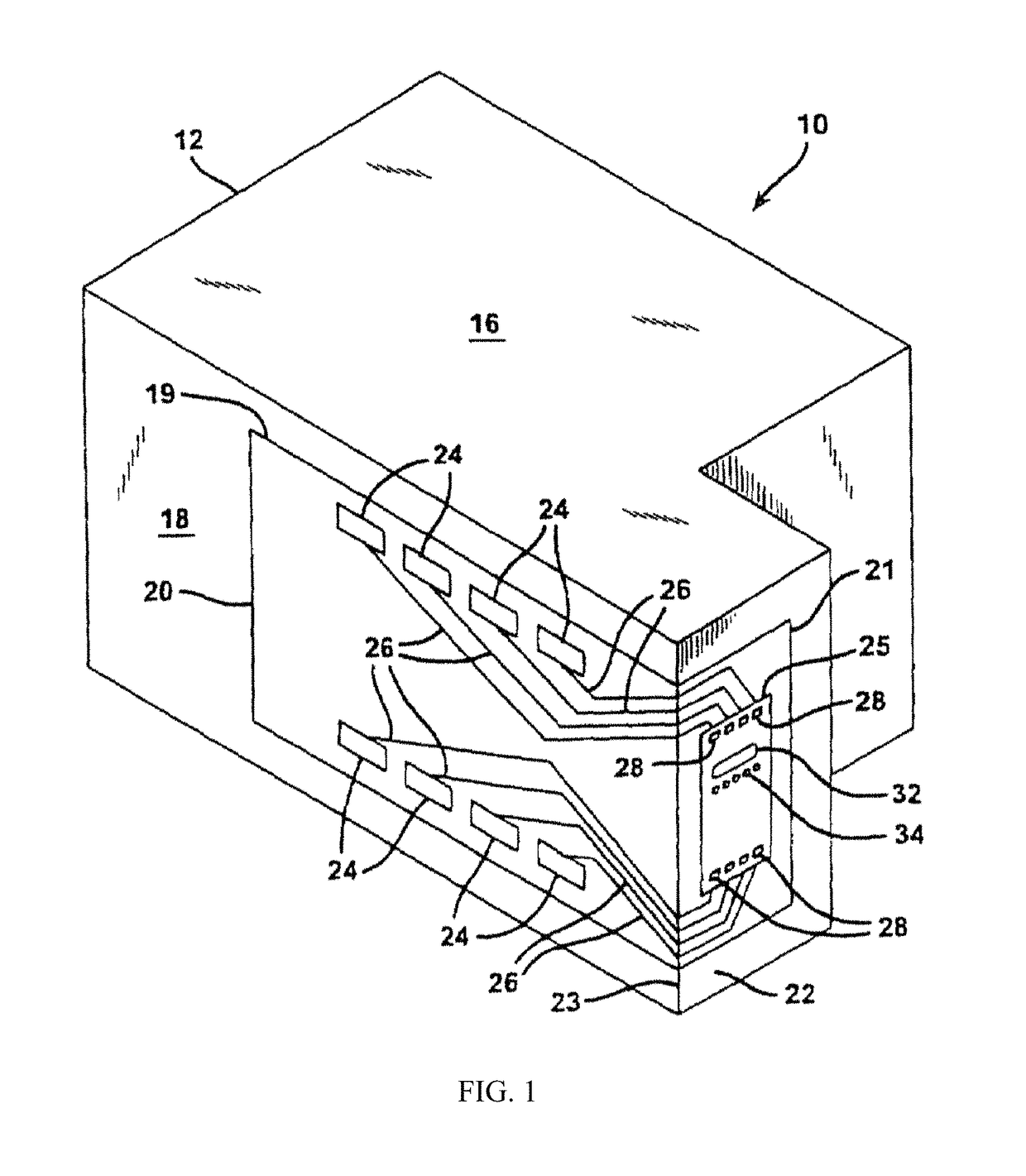
[0020]With reference to FIG. 1, an inkjet printhead of the present invention is shown generally as 10. The printhead 10 has a housing 12 formed of any suitable material for holding ink. Its shape can vary and often depends upon the external device that carries or contains the printhead. The housing has at least one compartment 16 internal thereto for holding an initial or refillable supply of ink. In one embodiment, the compar...


PUM


Abstract

A printhead including a fluid ejector chip having an electrical interface. The electrical interface includes one or more inputs for receiving respective primitive address data and heater address data corresponding to each of one or more address cycles, at least one of the one or more inputs being switchable to a deactivated state, and one or more shift registers, a total number of shift registers being adjustable so that each of the one or more shift registers corresponds to a respective one of the one or more inputs that is not in a deactivated state, the one or more shift registers receiving the respective primitive address data and heater address data from the one or more inputs that are not in a deactivated state to allow for selective application of electrical signals to the heating elements so that fluid is ejected from the fluid ejector chip in accordance with image data.

Description

FIELD[0001]This invention is related to inkjet printheads, and in particular, to systems and methods for controlling inkjet printheads.BACKGROUND[0002]Developing a configurable architecture for an inkjet heater chip allows for multiple applications of the design as well as more opportunities for Original Equipment Manufacturer (OEM) vendors. One of the fundamental specifications of a chip is the number of required data input pads and the rate at which serial data is clocked to the chip. These design variables are inversely related; reducing the number of inputs would require an increase in the clock rate in order to transfer the same amount of data.[0003]In a consumer printer application where minimizing printer cost is a design goal, it would be advantageous to use the traditional method of serial communication from the print engine to a passive carrier card along a ribbon cable. The resistive and capacitive nature of the ribbon cable itself limits the rate at which data can be rel...

Claims


Application Information

Patent Timeline
Patent Type & Authority Patents(United States)
IPC IPC(8): B41J2/14B41J2/045
CPCB41J2/14072B41J2/04543B41J2/0458B41J2202/13
Inventor EDELEN, JOHN GLENNSEMLER, NICOLE
Owner FUNAI ELECTRIC CO LTD
Why Eureka
Eureka Blog
Learn More