Inhaler with a pinch clamp

a technology of inhaler and pinch clamp, which is applied in the field of inhalers, can solve the problems of poor craving score and cessation rate, device is difficult to seal, and the dosing is not predictabl

Active Publication Date: 2020-01-28
KIND CONSUMER LIMITED
View PDF34 Cites 0 Cited by
  • Summary
  • Abstract
  • Description
  • Claims
  • Application Information

AI Technical Summary

Benefits of technology

[0018]By clamping a deformable tube, the present invention has a number of advantages. The clamping mechanism is simple as all that is required is a movable component to pinch the tube which need not be complex. Further, as the flow path is along an opened tube, there is no need for a tortuous flow which may otherwise be required to flow around an unseated valve component such as those in U.S. Pat. No. 6,889,687. The non-metered valve which allows uninterrupted flow allows a user to regulate the dose that they receive from the inhaler, as it will continue to dispense for as long as the user sucks.
[0019]The pinched tube arrangement lends itself well to an unmetered dosage. Also, while the device may be provided with the clamping member which effectively “snaps” open to provide a “binary” device which is either open or closed, the pinched deformable tube is well suited to a device in which the degree of opening of the tube is proportional to the strength of the suction. Such an outlet valve which is breath-operable and of varied resistance according to the inhalation profile it is actuated by, allows the user to self-titrate the inhaled dose in a continuous manner. This has applications firstly for smoking cessation inhaler devices where users want to self-titrate their dose of nicotine in a manner that fits their need, but also in other area such a pain management, diabetes, asthma and COPD where self-administered doses are preferable via the oral route.
[0026]The or each vane may be exposed to a through-flow of air such that, as a user sucks on the outlet, the through-flow of air impinges on an outer surface of the vane to move it inwardly. However, preferably, the or each vane is supported by a flexible membrane. This flexible membrane creates a chamber in which the vane is housed and which is open to the outlet, but is otherwise sealed, with the face of the membrane on the opposite side to the vane being open to atmospheric pressure. When a user sucks on the outlet, they create a negative pressure within the chamber to move the vane and the membrane flexes to allow this movement. This provides a very efficient mechanism for conveying the suction force to the vane.

Problems solved by technology

Thus, a smoker is able to obtain the “hit” that is familiar from a cigarette, rather than having to deal with the slow release from a patch or gum which does not produce such a hit which leads to unpredictable dosings and poor craving scores and cessation rates.
This arrangement only ever allows a user to inhale one metered dose no matter how long they suck on the device.
Such a device is difficult to seal in the first position.
It will also require considerable force in order to suck the tongue to the open position against the action of a retaining spring and the relatively large mass of the tongue means that it will be difficult to return to the closed position meaning that dispensing will continue after the suction has been removed.
However, the mechanism is reasonably complex, has a tortuous flow path which is likely to impede delivery of the composition from the reservoir, and is “binary” in nature in the sense that the valve is either open or closed.
It does not provide the ability for the user to regulate the amount of flow by varying the degree of suction.
Such an axially movable plunger is undesirable in practice as it has been found that the level of suction required to overcome the spring biasing force is too high to be usable in practice.
Again, this suffers from problems of complexity, lack of control and a tortuous flow path.
While this solves some of the problems in that it provides a simple mechanism and an axial flow path, the force required as suction to trigger the device is comparatively large and the user, as a result, can exert less control over the system to release a variable dose, small or large according to the inhalation intake.

Method used


Image

  • Inhaler with a pinch clamp
  • Inhaler with a pinch clamp
  • Inhaler with a pinch clamp

Examples


Embodiment Construction

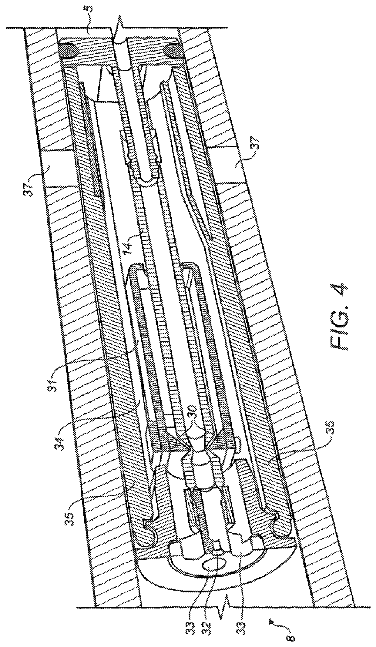
[0037]The present invention relates to an improvement of the outlet valve for a breath-activated cigarette and only this aspect of the invention will be specifically described here. For details of the construction of the remainder of the cigarette device and its refill mechanism, reference is made to WO 2009 / 001078.

[0038]The first example of an inhaler in accordance with the present invention is shown in FIGS. 1 to 3.

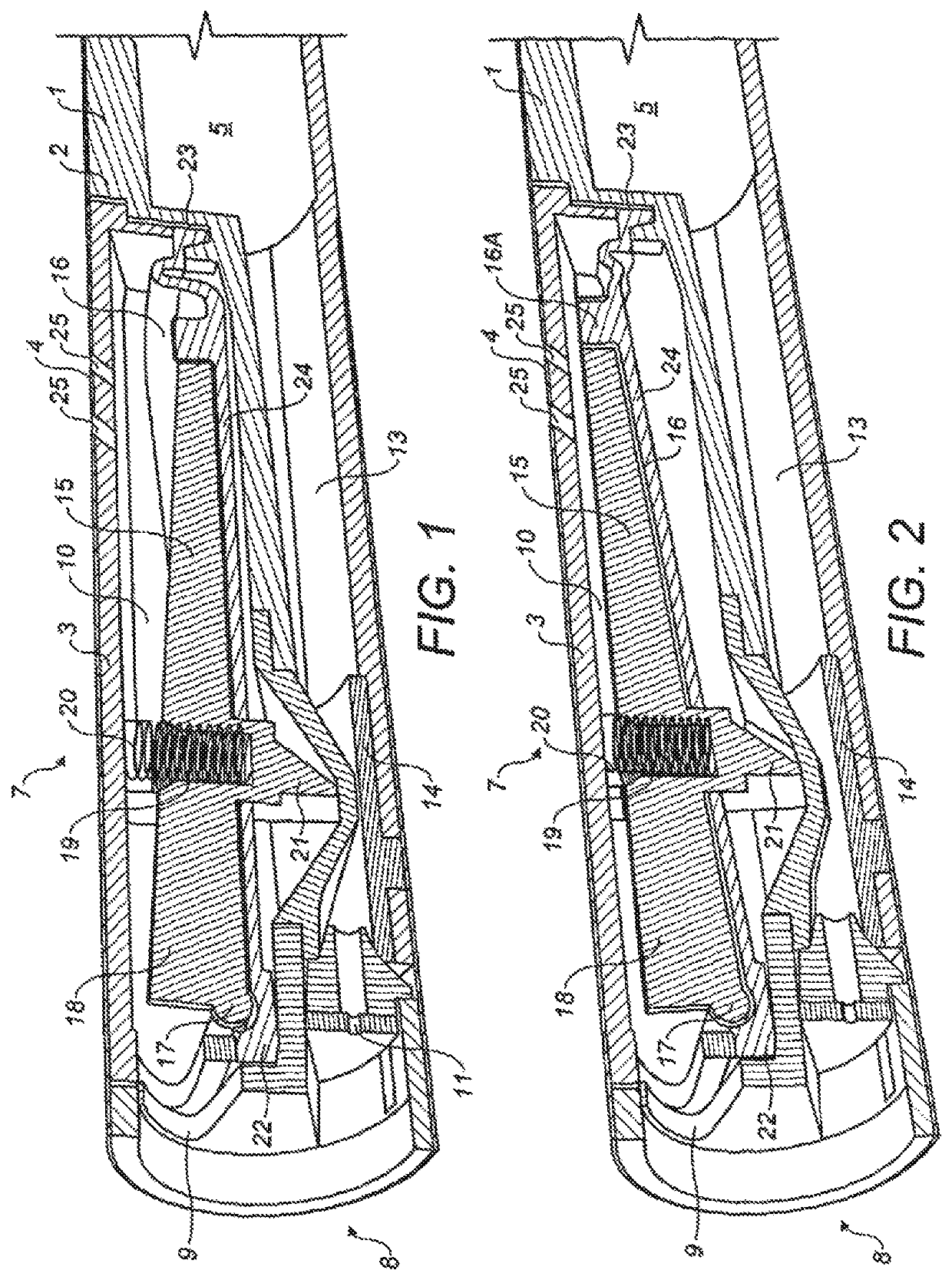
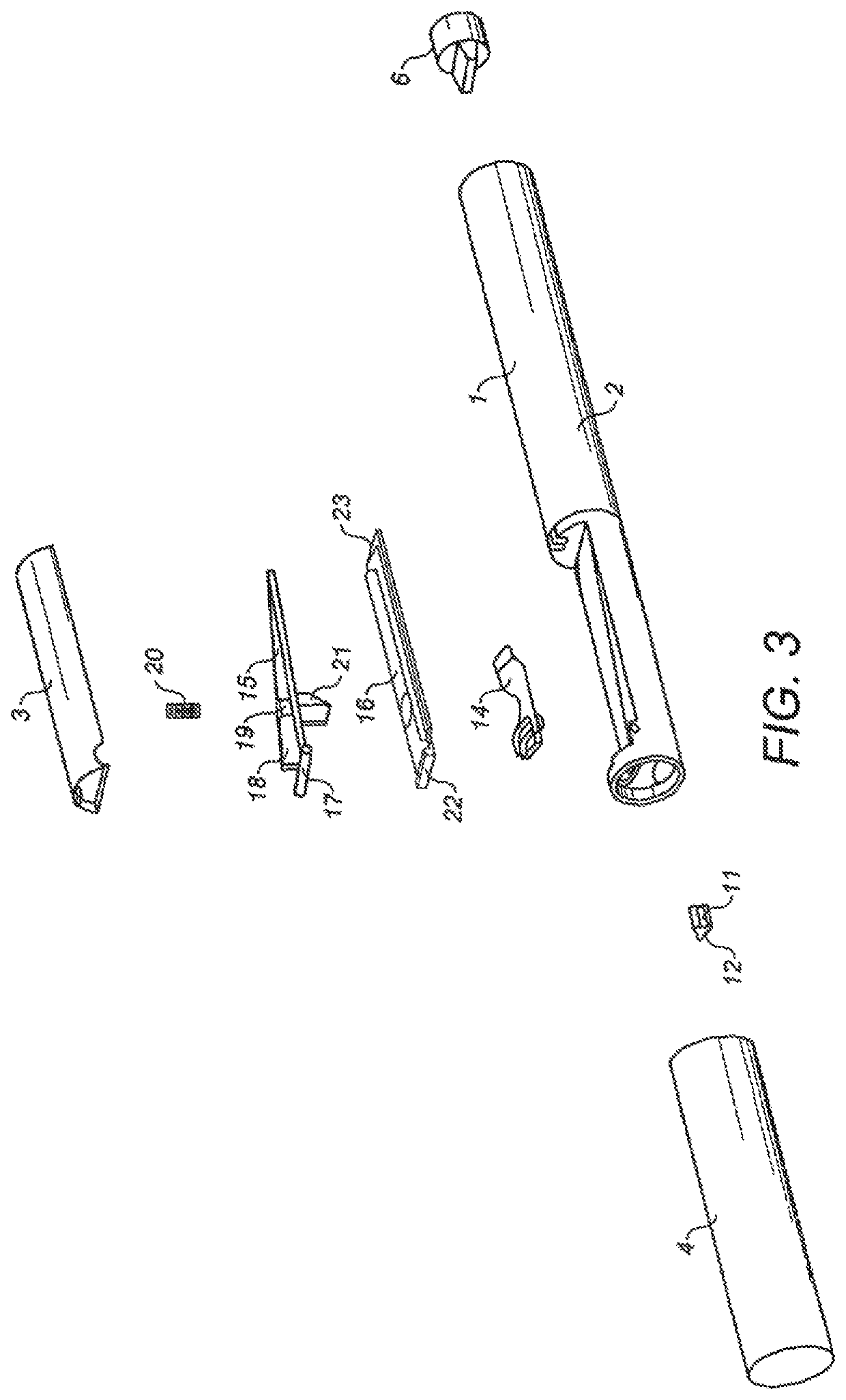
[0039]The device has a housing 1 made up of a main chassis 2 and a closure element 3 as shown in FIG. 1. This is held in place by label 4. Within the housing, there is a reservoir 5 containing the inhalable composition. This is preferably pressurised but could also work with a non-pressurised reservoir in combination with a Venturi nozzle to generate an enhanced suction force on the reservoir, or a non-pressurised reservoir containing a substance that is prone to evaporating at room temperature. It may be refillable as described in WO 2009 / 001082 through the filling val...


PUM


Abstract

An inhaler comprising a reservoir of an inhalable composition with an outlet at one end through which the inhalable composition is discharged. A non-metered breath-activated valve is provided between the one end and the reservoir, the breath-activated valve comprising a flow path extending from the reservoir to the outlet end. At least a portion of the flow path is a deformable tube. A clamping member pinches the deformable tube closed when no suction force is applied to the device and releases the tube to open the flow path when suction is applied at the outlet, to provide uninterrupted flow from the reservoir to the outlet.

Description

CROSS-REFERENCE TO RELATED APPLICATIONS[0001]This application is a continuation of U.S. patent application Ser. No. 13 / 389,434, filed Feb. 7, 2012, which is herein incorporated by reference in its entirety.BACKGROUND OF THE INVENTION[0002]Field of the Invention[0003]The present invention relates to an inhaler.[0004]Description of the Related Art[0005]The invention has been specifically designed for a simulated cigarette device having a generally cigarette-shaped body. However, the invention relates to a development of the outlet valve for such a device which has broader applications in the field of inhalers, for example, medicinal inhalers for oral drug delivery such as asthma inhalers.[0006]In the field of cigarette replacements, there have been a number of proposals to create a simulated cigarette. Such a device has a number of advantages over traditional nicotine replacement therapies such as patches and gum in that they recreate the physical act of smoking which is psychological...

Claims


Application Information

Patent Timeline
Patent Type & Authority Patents(United States)
IPC IPC(8): A61M15/00A24F47/00A61M15/06A61M16/20A24F42/20A24F42/60
CPCA24F40/485A61M15/06A61M15/0093A61M16/20A61M15/0091A61M2205/8225A24F42/20A24F42/60A61M16/205A61M16/207
Inventor HEARN, ALEXMCDERMENT, IAIN
Owner KIND CONSUMER LIMITED
Why Eureka
Try Eureka