Process for atomic layer deposition

a technology of atomic layer and deposition method, which is applied in the direction of chemical vapor deposition coating, coating, additive manufacturing apparatus, etc., can solve the problems of insensitive to transport non-uniformities, difficult to avoid some direct reaction of different precursors, and impair surface uniformity

Active Publication Date: 2007-10-11
EASTMAN KODAK CO
View PDF5 Cites 100 Cited by
  • Summary
  • Abstract
  • Description
  • Claims
  • Application Information

AI Technical Summary

Benefits of technology

[0037] It is an advantage of the present invention that it provides a compact process for atomic layer deposition onto a substrate, well suited to a number of different types of substrates and deposition environments.
[0038] It is a further advantage of the present invention that it allows operation, in preferred embodiments, under atmospheric pressure conditions.
[0039] It is yet a further advantage of the present invention that it is adaptable for deposition on a web or other moving substrate, including deposition onto a large area substrate.
[0040] It is still a further advantage of the present invention that it can be employed in low temperature processes at atmospheric pressures, which process may be practice in an unsealed environment, open to ambient atmosphere.

Problems solved by technology
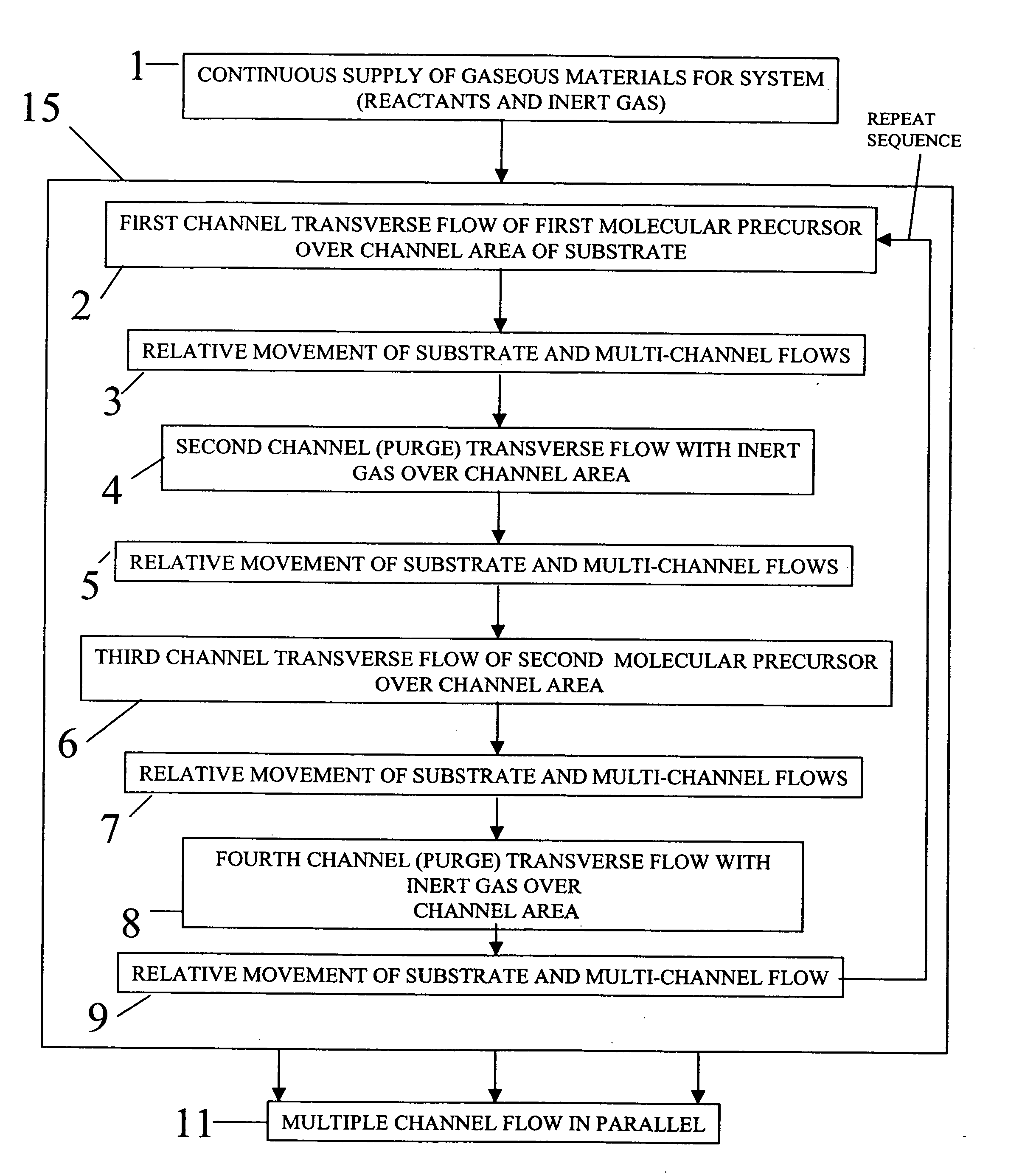
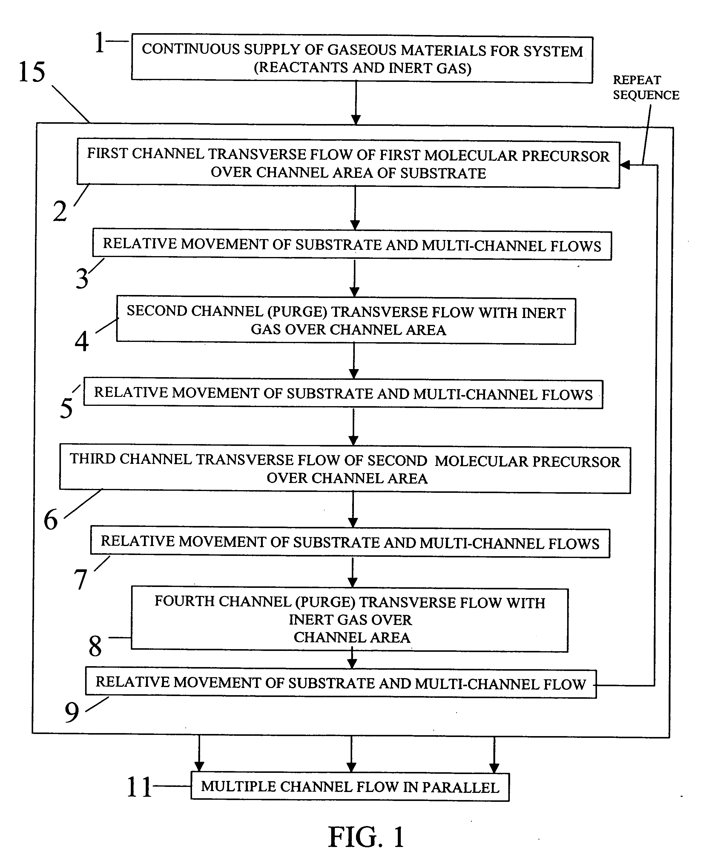
In practice in any process it is difficult to avoid some direct reaction of the different precursors leading to a small amount of chemical vapor deposition reaction.
Self-saturating surface reactions make ALD insensitive to transport non-uniformities, which might otherwise impair surface uniformity, due either to engineering tolerances and the limitations of the flow process or related to surface topography (that is, deposition into three dimensional, high aspect ratio structures).
As a general rule, a non-uniform flux of chemicals in a reactive process generally results in different completion times at different areas.
However, in order to take advantage of its inherent capabilities a number of technical hurdles still remain.
However, it is difficult to obtain a reliable scheme for introducing the needed series of gaseous formulations into a chamber at the needed speeds and without some unwanted mixing.
Existing ALD approaches have been compromised with the trade-off between the need to shorten reaction times and improve chemical utilization efficiency, and on the other hand, the need to minimize purge-gas residence and chemical removal times. One approach to overcome the inherent limitations of “pulsed” delivery of gaseous material is to provide each reactant gas continuously and to move the substrate through each gas in succession.
While processes such as those described in the '563 Yudovsky and '022 Suntola et al. disclosures may avoid some of the difficulties inherent to pulsed gas approaches, these processes have other drawbacks.
Driving the gas flow directly toward the surface in a vertical direction, as described in both of these disclosures, invites barrier layer effects that complicate gas flow and can cause unwanted mixing.
This prevents these devices from being compact and increases the needed travel distance of the substrate in order to effect ALD exposure.
Moreover, it would be very difficult to maintain a uniform vacuum at different points in an array and to maintain synchronous gas flow and vacuum at complementary pressures, thus compromising the uniformity of gas flux that is provided to the substrate surface.
The complex arrangements of both the gas flow delivery unit of the '563 Yudovsky disclosure and the gas flow array of the '022 Suntola et al. disclosure, each providing both gas flow and vacuum, make these solutions difficult to implement and costly to scale and limit their potential usability to deposition applications onto a moving substrate of limited dimensions.
Conventional designs for ALD processes, however, would not easily offer this flexibility.
For example, conventional approaches offer little promise of obtaining an ALD gas distribution process that could be transported across the surface of a larger substrate or web arrangement.

Method used


Image

  • Process for atomic layer deposition
  • Process for atomic layer deposition
  • Process for atomic layer deposition

Examples


example 1

[0141] This example shows the production of a zinc oxide semiconductor film according to the present invention used to produce a working thin film transistor. In this structure, the gate of the device is a heavily doped silicon wafer, and the insulator is a film of silicon dioxide grown by a thermal process on the silicon wafer prior to deposition of the zinc oxide semiconducting film.

[0142] The zinc oxide semiconductor layer was applied using the inventive deposition system. Two runs were made with the substrate temperature at 200° C. and the following conditions:

TABLE 1MetalDiethylzincPrecursorWaterOxidizerNitrogenBubblerDilutionAirBubblerDilutionPurgeBlowFlowFlowFlowFlowFlowSample(sccm)(sccm)(sccm)(sccm)(sccm)(sccm)Cycles1-A1062051010001500401-B 56205 51000150040

[0143] After deposition of the zinc oxide, aluminum contacts were applied to the above devices by evaporation through a shadow mask to a thickness of 500 A. The shadow mask produced devices with a channel width of 500 ...

example 2

[0145] This example shows the production of aluminum oxide films according to the present invention, demonstrating the capability to make high quality insulating films with good breakdown voltage. In this structure, a bare silicon wafer is used as one electrode on which is grown a film of aluminum oxide using the inventive equipment described above.

[0146] The aluminum oxide layers were applied with the substrate at 200° C. and the following deposition conditions, where 2-B is a replicate data point.

TABLE 3Trimethyl-MetalAluminumPrecursorWaterOxidizerNitrogenBubblerDilutionAirBubblerDilutionPurgeBlowFlowFlowFlowFlowFlowSample(sccm)(sccm)(sccm)(sccm)(sccm)(sccm)Cycles2-A106201010110015001002-B106201010110015001002-C106201010110015002002-D20620102011001500100

[0147] After deposition of the aluminum oxide, samples were measured for thickness and refractive index using ellipsometry. After that, aluminum contact pads were applied to the top of the sample D film using shadow mask evapora...

example 3

[0149] This example shows the production of a working transistor device using heavily doped silicon as the gate material but then employing Al2O3 as the dielectric and ZnO as the semiconductor, in which both of the latter materials are deposited using the present invention.

[0150] The aluminum oxide films were deposited first according to following conditions:

TABLE 5Trimethyl-MetalAluminumPrecursorWaterOxidizerNitrogenBubblerDilutionAirBubblerDilutionPurgeFlowFlowFlowFlowFlowFlowSample(sccm)(sccm)(sccm)(sccm)(sccm)(sccm)Cycles3-A25620102011001500803-B2562010201100150060

[0151] After the aluminum oxide deposition, both samples were coated using the above apparatus with ZnO according to the following conditions:

TABLE 6Diethyl-MetalzincPrecursorWaterOxidizerNitrogenBubblerDilutionAirBubblerDilutionPurgeFlowFlowFlowFlowFlowFlow(sccm)(sccm)(sccm)(sccm)(sccm)(sccm)Cycles56205101000150020

[0152] Aluminum contacts were evaporated on the resulting multilayer device through a shadow mask, y...


PUM

PropertyMeasurementUnit
speedaaaaaaaaaa
temperatureaaaaaaaaaa
distanceaaaaaaaaaa

Abstract

The present invention relates to a deposition process for thin film deposition onto a substrate comprising providing a plurality of gaseous materials comprising at least first, second, and third gaseous materials, wherein the first and second gaseous materials are reactive with each other such that when one of the first or second gaseous materials are on the surface of the substrate the other of the first or second gaseous materials will react to deposit a layer of material on the substrate and wherein the third gaseous material is inert with respect to reacting with the first or second gaseous materials. The process comprises flowing the gaseous materials along the length direction of a plurality of elongated channels across the surface of the substrate surface in close proximity thereto.

Description

CROSS-REFERENCE TO RELATED APPLICATIONS [0001] The present application is related to U.S. application Ser. No. (docket 91865), filed concurrently herewith by Levy et al. and entitled, “APPARATUS FOR ATOMIC LAYER DEPOSITION.”FIELD OF THE INVENTION [0002] This invention generally relates to the deposition of thin-film materials and, more particularly, to a process for atomic layer deposition onto a substrate using a distribution manifold allowing transverse gas flow across a substrate. BACKGROUND OF THE INVENTION [0003] Among the techniques widely used for thin-film deposition are Chemical Vapor Deposition (CVD) that uses chemically reactive molecules that react in a reaction chamber to deposit a desired film on a substrate. Molecular precursors useful for CVD applications comprise elemental (atomic) constituents of the film to be deposited and typically also include additional elements. CVD precursors are volatile molecules that are delivered, in a gaseous phase, to a chamber in orde...

Claims


Application Information

Patent Timeline
Patent Type & Authority Applications(United States)
IPC IPC(8): H01L21/31H01L21/469
CPCC23C16/403C23C16/407C23C16/45504C23C16/545C23C16/45551C23C16/45591C23C16/45519B33Y80/00C23C16/45525
Inventor LEVY, DAVID H.
Owner EASTMAN KODAK CO
Why Eureka
Try Eureka