Dental impression coping with retention

a technology of dental impressions and copings, applied in the field of dental impression copings, can solve the problems of inability to fully fully realize the effect of the impression, prone to inaccuracy, and more complex techniques, and achieve the effects of reducing costs, saving valuable time, and less prone to jams or wedges

Inactive Publication Date: 2006-06-27
ZIMMER DENTAL INC
View PDF108 Cites 92 Cited by
  • Summary
  • Abstract
  • Description
  • Claims
  • Application Information

AI Technical Summary

Benefits of technology

[0017]As one important advantage of the present invention, connection between the coping and implant does not require a separate retaining screw. Rather, the connection occurs with active or moveable biasing and locking members. Since a retaining screw is not needed, several steps can be eliminated while performing an open-tray impression technique. These steps include: threading the screw into the implant; opening or drilling holes in the impression tray; and unthreading the screw prior to removing the coping from the implantation site. The elimination of these steps saves valuable time during the dental surgery and reduces costs.
[0018]As another advantage, the connection between the coping and implant will not damage the internal cavity of the implant and offers a reliable, consistent engagement with the implant.
[0019]As another advantage, the retention mechanism is well suited for multi-teeth restorations, especially when some of the implants are angled with respect to one another. In this situation, when the implants are not all vertically oriented, the copings are less prone to jam or wedge when the impression tray is lifted and removed from the mouth of the patient.
[0020]As yet another advantage, the retention mechanism is durable and formed of a corrosive resistant and biocompatible material well suited for implant dentistry. This mechanism is easily manufactured and connected to the distal portion of the body.
[0021]Accordingly, the present invention comprises a combination of features and advantages that overcome various problems, deficiencies, or shortcomings associated with prior devices. The various features and advantages of the invention will be readily apparent to those skilled in the art upon referring to the accompanying drawings and reading the following detailed description of the preferred embodiments of the invention.

Problems solved by technology

The technique, however, is sometimes prone to inaccuracies where sufficient care is not taken during the step of reinserting the coping into the impression material.
The open-tray technique is generally preferred for accuracy, but it is more complex since holes or apertures may need to be cut in the tray.
As a result, this technique often takes more time to prepare and execute.

Method used


Image

  • Dental impression coping with retention
  • Dental impression coping with retention
  • Dental impression coping with retention

Examples


Embodiment Construction

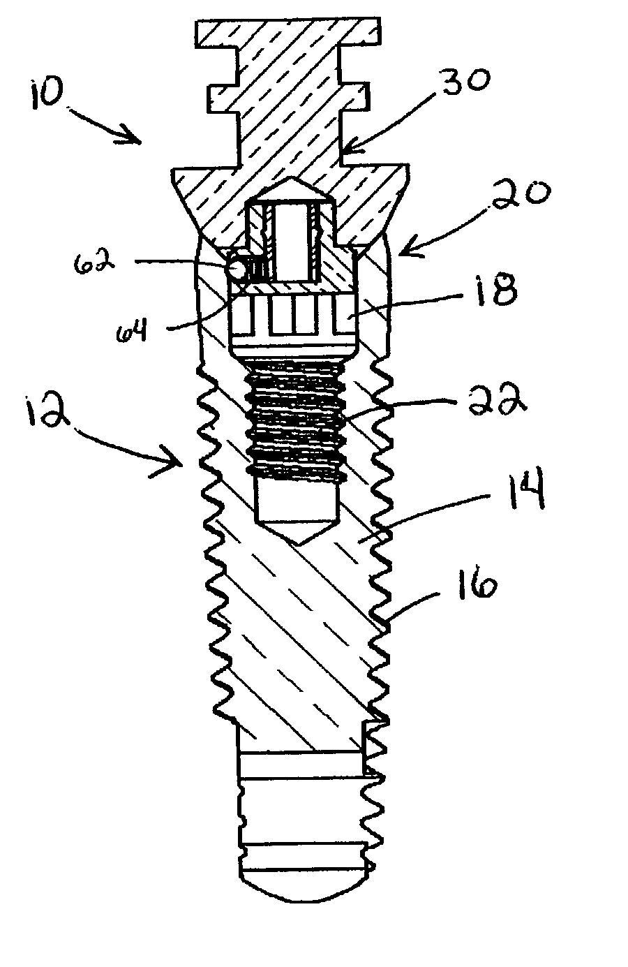
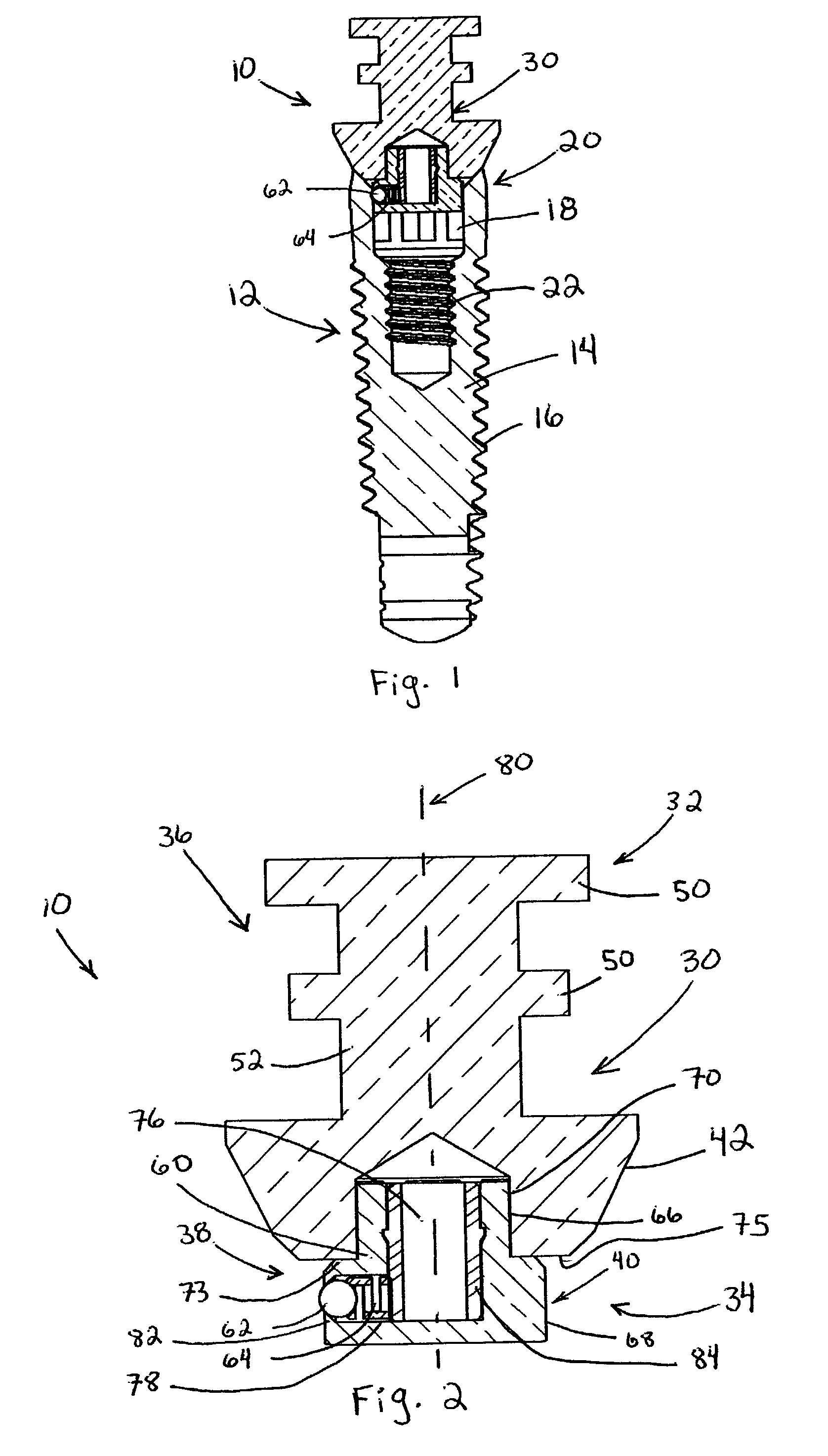
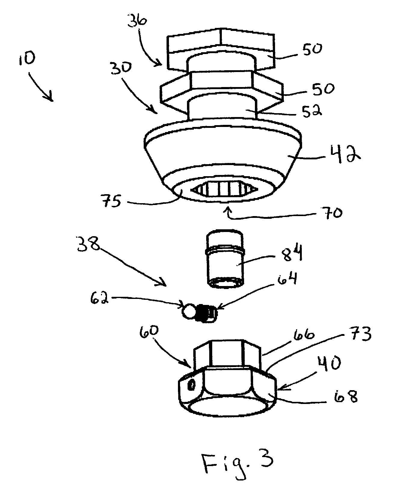
[0013]The present invention is directed toward an impression coping for taking an accurate impression of a dental implant installed in the jawbone of a patient. The impression coping has a body that extends from a proximal portion to a distal portion. The distal portion is configured and adapted to be secured to the implant, and the proximal portion includes an attachment portion adapted to be embedded in an impression material. Preferably, two attachment members form part of the attachment portion and comprise separate, spaced polygons that project outwardly from the body.

[0014]A retention mechanism is located on the body at the distal portion. The retention mechanism is sized and shaped to engage the coronal end of the implant and includes a housing having a locking member and a biasing member. Preferably, the housing forms a bore perpendicular to a longitudinal axis that runs through the body. At one end of the bore, the biasing member is positioned to bias the locking member. Th...


PUM


Abstract

An impression coping for taking an impression of a dental implant installed in the jawbone of a patient. The impression coping has a proximal end with an impression portion adapted to be embedded in impression material and a distal portion with a retention mechanism. The retention mechanism includes a housing having a locking member and biasing member. The locking member is biased to slideably move in the housing and engage the dental implant.

Description

CROSS-REFERENCE TO RELATED APPLICATIONS[0001]This application claims benefit of priority of U.S. Provisional Application Ser. No. 60 / 410,073 filed Sep. 12, 2002.FIELD OF THE INVENTION[0002]The present disclosure relates to dental impression copings for taking impressions of a dental implant site from which accurate models can be constructed. More particularly, the invention relates to an improved impression coping that utilizes a retention mechanism to connect with the dental implant.BACKGROUND OF THE INVENTION[0003]Implant dentistry involves the restoration of an edentulous area in the mouth of a patient. The restorative techniques typically use artificial components, such as abutments and prosthetic teeth that are secured to a dental implant. According to state of the art techniques, this restorative process has several stages.[0004]During an initial stage, the jawbone of the patient is exposed, and a series of drills are used to form a cylindrical cavity (the osteotomy) in the bo...

Claims


Application Information

Patent Timeline
Patent Type & Authority Patents(United States)
IPC IPC(8): A61C8/00
CPCA61C8/0001
Inventor KUMAR, AJAYARAVENA, INES
Owner ZIMMER DENTAL INC
Why Eureka
Try Eureka