Exhaust line assembly for a bottle attachment apparatus

a bottle attachment and exhaust line technology, applied in the direction of liquid handling, instruments, glassware laboratories, etc., can solve the problems of contamination of the operator's hand, interference with the handling of the bottle attachment apparatus, and splashing of potentially toxic or caustic liquid adhering to the closure cap, etc., to achieve the effect of length toleran

Active Publication Date: 2017-12-05
BRAND GMBH CO KG
View PDF33 Cites 0 Cited by
  • Summary
  • Abstract
  • Description
  • Claims
  • Application Information

AI Technical Summary

Benefits of technology

[0031]When the closure cap meets the tip of the exhaust line, the pivoting movement of the mounting lug with the closure cap may lead to the radial spacing from the rotary joint being somewhat different from that in the final closure position of the closure cap on the tip. In order to achieve optimization in the construction and to keep the closure cap on the tip free from interfering forces also under these circumstances, it is recommended that a length compensator is provided between the rotary joint and the closure cap. The effective length of the mounting lug between the rotary joint and the closure cap may thus slightly vary, depending on the position of the mounting lug. This may be implemented, for example, by a limited telescopic design of the material strip forming the mounting lug. However, this may be implemented in a particularly simple and expedient manner on the rotary joint and / or on the closure cap.
[0033]Fastening of the mounting lug to the mount of the exhaust line assembly is implemented in a particularly expedient manner in that the bearing eyelet is configured so as to be open to one side, having an opening of which the passage dimension is smaller than the diameter of the bearing journal in such a manner that the bearing eyelet, utilizing the inherent elasticity thereof, is push-fittable in a latching manner onto the bearing journal. The openings are dimensioned such that the force which has to be applied for assembly and disassembly is in excess of a multiple of the force of the dead weight of the mounting lug with the closure cap. The mounting lug with the closure cap is therefore securely suspended in the rotary joint; nevertheless, the mounting lug with the closure cap may be assembled and disassembled in an efficient manner. The embodiment of the bearing eyelet or bearing eyelets as a slotted eyelet or slotted eyelets, respectively, guarantees a length tolerance of the mutually interacting components which is expedient in practical use.

Problems solved by technology

This interferes with the handling of the bottle attachment apparatus.
If and when the closure cap impacts anywhere in an uncontrolled manner, splashing of potentially toxic or caustic liquid adhering to the closure cap may arise.
The unwanted result is contamination of the operator's hand and a carryover of the liquid to other objects.
On account of the mounting lug being deformed in a more or less arcuate manner, flexural stress which causes friction in the eyelet-and-groove connection and impedes rotatability of the closure cap at the end of the mounting lug arises in the mounting lug when the closure cap in the closed position sits on the tip.
Friction may be so intense that the eyelet is conjointly rotated, the material strip is warped, and rotatability is completely blocked.
The arc of the material strip then even impedes manual releasing of the closure cap, and the back of the hand may contact the arc during the rotational movement.

Method used


Image

  • Exhaust line assembly for a bottle attachment apparatus
  • Exhaust line assembly for a bottle attachment apparatus
  • Exhaust line assembly for a bottle attachment apparatus

Examples


Embodiment Construction

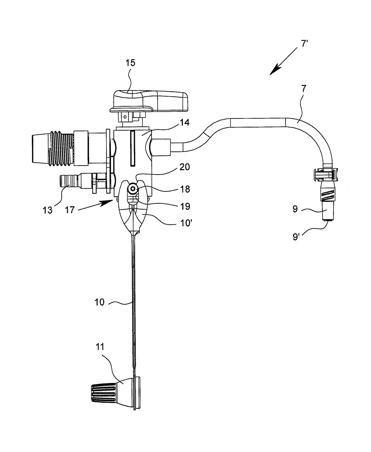
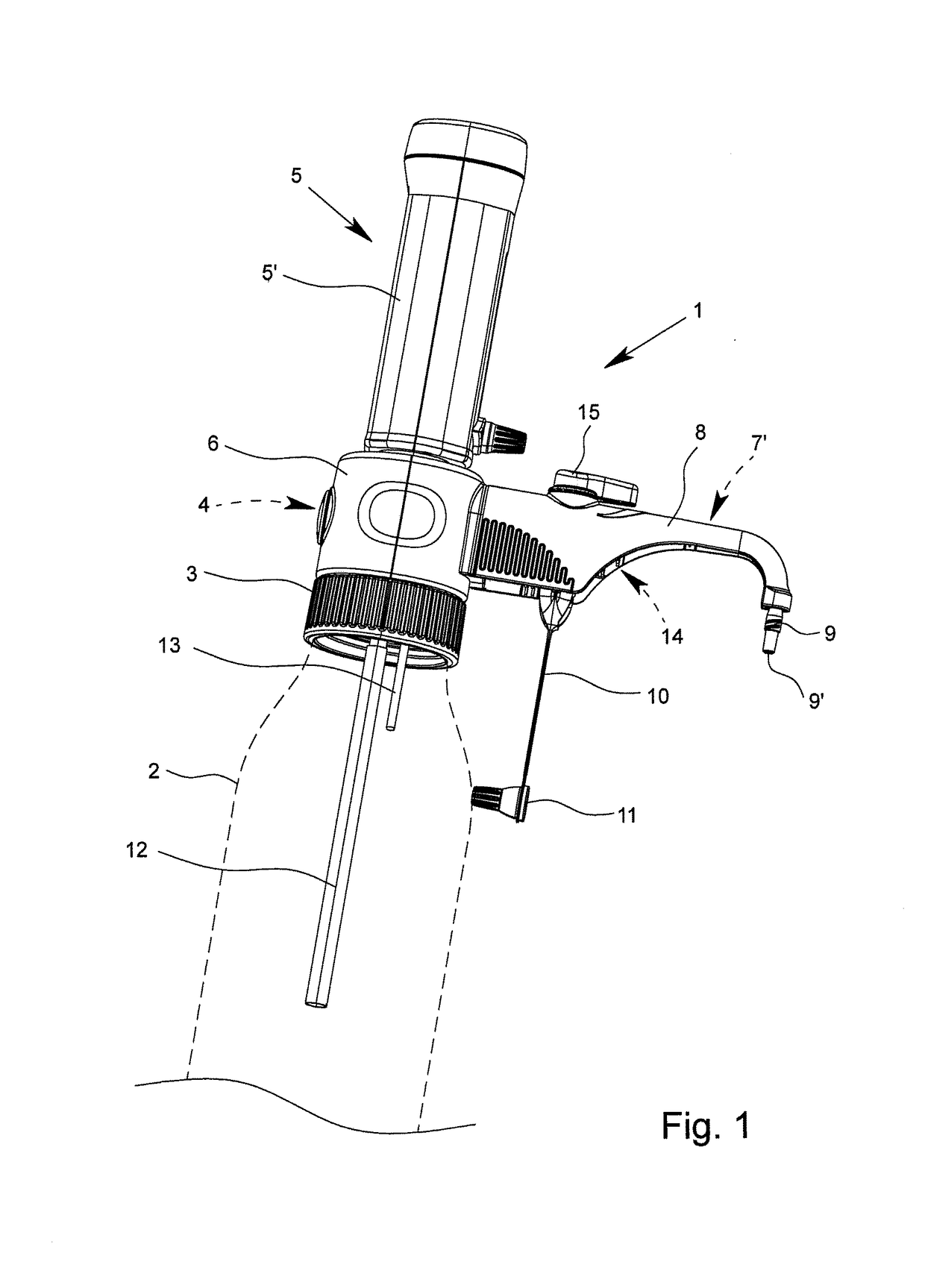
[0046]FIG. 1 shows a preferred exemplary embodiment of a bottle attachment apparatus 1 according to the invention for handling liquids, herein in the form of a bottle top dispenser.

[0047]In general terms, in respect of bottle attachment apparatuses for handling liquids, i.e., so-called “liquid handling” apparatuses, reference may be made to the general catalog of the applicant (BRAND general catalog 900 [June 2013]). Bottle attachment apparatus of the type being discussed are comprehensively explained therein in terms of construction and application. Moreover, in respect of bottle attachment apparatuses of the type being discussed, reference may also be made to the sources of the prior art, as stated at the outset.

[0048]The definitions pertaining to top and bottom, and to front and rear, which have been stated at the outset of the description, apply to the bottle attachment apparatus which is described here in the preferred exemplary embodiment. The bottle attachment apparatus 1 is ...


PUM


Abstract

An exhaust line assembly for a bottle attachment apparatus for handling liquids has an outrigger-type mount, an exhaust line which is disposed and guided in the mount and which terminates in a tip, and a mounting lug which has a closure cap attached to the end thereof and which is fastened to the exhaust line assembly, the tip of the exhaust line being closable by way of the closure cap. The mounting lug at that end thereof which is fastened to the exhaust line assembly is articulated so as to be pivotable by a rotary joint which has a physically present axis of rotation.

Description

BACKGROUND OF THE INVENTION[0001]Field of the Invention[0002]The invention relates to an exhaust line assembly for a bottle attachment apparatus for handling liquids, and to a bottle attachment apparatus for handling liquids.[0003]Description of Related Art[0004]In the case of bottle attachment apparatuses for handling liquids, the focus is on precisely measuring and conveying liquids from a storage bottle or another storage container, wherein precise measuring is performed when a partial volume of liquid is received from the storage bottle or similar into the apparatus and / or when a partial volume of liquid is externally dispensed from the apparatus into a container.[0005]Bottle attachment apparatuses of the type being discussed are in particular bottle top dispensers and burets. Bottle attachment apparatuses of this type are widely used in chemical, biological, and pharmaceutical laboratories and production facilities.[0006]The term “liquid” in the present context preferably refer...

Claims


Application Information

Patent Timeline
Patent Type & Authority Patents(United States)
IPC IPC(8): B67C3/26B05B11/00G01F11/02B67C3/28B01L3/02
CPCB67C3/2634B01L3/0293B05B11/0032B67C3/28G01F11/028B05B11/3015B01L2400/0478B01L2400/0605B05B11/3007B65D47/0857G01F11/04G01F11/28B65D2547/06B05B11/1007B05B11/1015
Inventor BOHM, DIETERERTL, MICHAEL
Owner BRAND GMBH CO KG
Why Eureka
Try Eureka