
Defect correction using tomographic scanner for additive manufacturing

a tomographic scanner and additive manufacturing technology, applied in the field of additive manufacturing, can solve the problems of preventing the object from conforming, thermal defects that cannot be identified during additive manufacturing, and thermal defects that are difficult to identify after manufacturing

Active Publication Date: 2017-12-05
GENERAL ELECTRIC CO
View PDF41 Cites 29 Cited by
  • Summary
  • Abstract
  • Description
  • Claims
  • Application Information

AI Technical Summary

Benefits of technology

The present patent aims to address certain problems and provide a solution. It describes the problem that needs to be solved and the expected effect of the patent.

Problems solved by technology

However, one challenge with the cooling of the object is that a thermal defect can form in the object upon cooling, which prevents the object from conforming to the intended 3D model.
The thermal defects typically cannot be identified during additive manufacturing because they are not present until later in the process.
The thermal defects can also be difficult to identify after manufacturing because they are dimensionally very small and, oftentimes, are located in the object's interior.
Current analysis techniques do not provide adequate mechanisms to identify the thermal defects and allow for corrections in the intended 3D model.

Method used


Image

  • Defect correction using tomographic scanner for additive manufacturing
  • Defect correction using tomographic scanner for additive manufacturing
  • Defect correction using tomographic scanner for additive manufacturing

Examples


Embodiment Construction

[0015]In the following specification and the claims, reference will be made to a number of terms, which shall be defined to have the following meanings:

[0016]“Optional” or “optionally” means that the subsequently described event or circumstance may or may not occur, and that the description includes instances where the event occurs and instances where it does not.

[0017]Approximating language, as used herein throughout the specification and claims, may be applied to modify any quantitative representation that could permissibly vary without resulting in a change in the basic function to which it is related. Accordingly, a value modified by a term or terms, such as “about”, “approximately” and “substantially”, are not to be limited to the precise value specified. In at least some instances, the approximating language may correspond to the precision of an instrument for measuring the value. Here and throughout the specification and claims, range limitations may be combined and / or interc...


PUM

PropertyMeasurementUnit
thickaaaaaaaaaa
computed tomographyaaaaaaaaaa
CTaaaaaaaaaa

Abstract

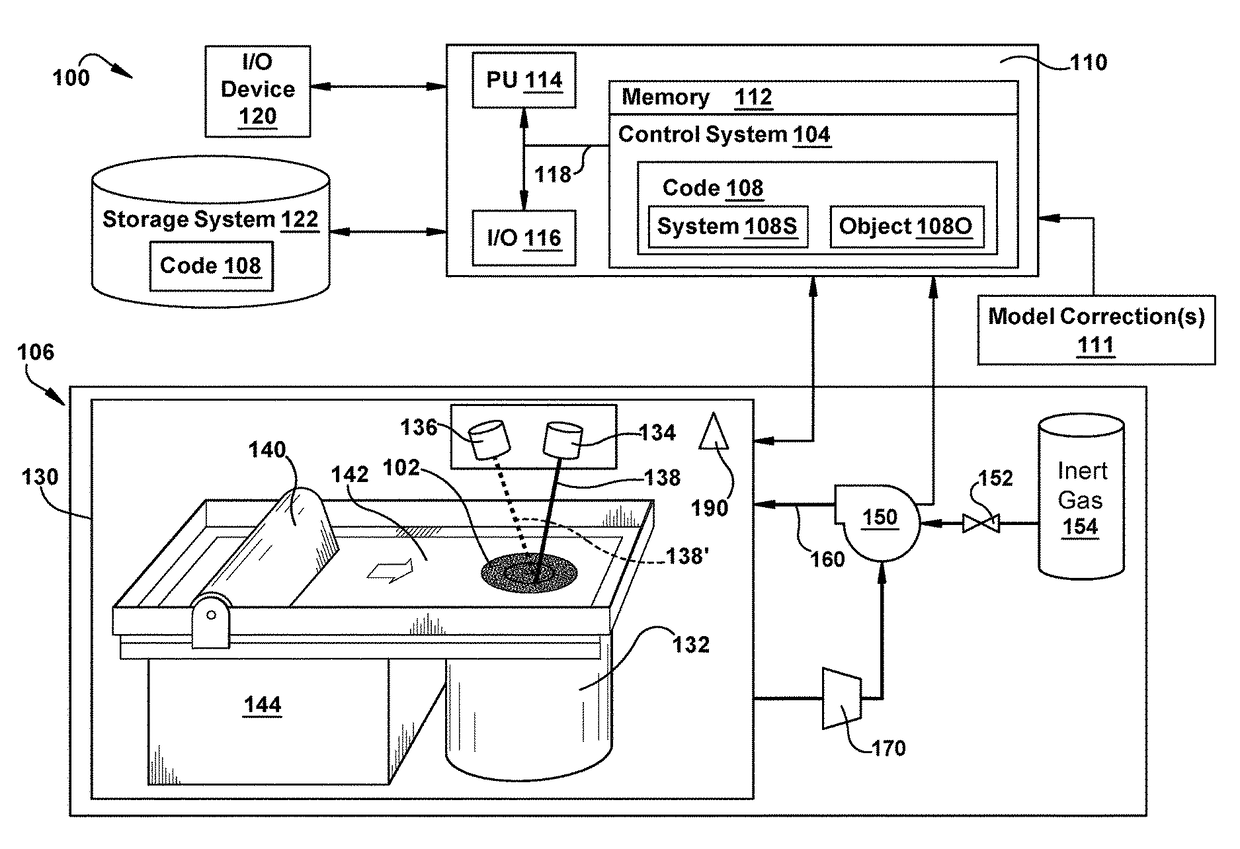
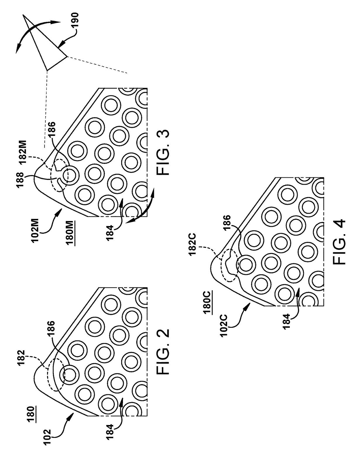
A method for correction of thermal defects using tomographic scanning for additive manufacturing is provided. The method may include forming a portion of an object using an additive manufacturing system based on an intended three-dimensional (3D) model of the object that is in an additive manufacturing system format. The portion of the object is scanned using a tomographic scanner to obtain a model of the portion of the object in a tomographic scanner format. The model is converted from the tomographic scanner format into the additive manufacturing system format to obtain a converted tomographic model; and the converted tomographic model is compared to the intended 3D model to identify a defect in the portion of the object. A modified 3D model may be generated of the object correcting the intended 3D model to address the defect of the portion of the object.

Description

BACKGROUND OF THE INVENTION[0001]The disclosure relates generally to additive manufacturing, and more particularly, to a method for correcting a three-dimensional model used for additive manufacturing based on defects identified using tomographic scanning.[0002]Additive manufacturing (AM) includes a wide variety of processes of producing an object through the successive layering of material rather than the removal of material. As such, additive manufacturing can create complex geometries without the use of any sort of tools, molds or fixtures, and with little or no waste material. Instead of machining objects from solid billets of material, much of which is cut away and discarded, the only material used in additive manufacturing is what is required to shape the object.[0003]Additive manufacturing techniques typically include taking a three-dimensional computer aided design (CAD) file of the object to be formed that includes an intended three-dimensional (3D) model or rendering of th...

Claims


Application Information

Patent Timeline
Patent Type & Authority Patents(United States)
IPC IPC(8): B29C35/08B28B11/00G01B11/00G01N23/04B29C45/76
CPCG01N23/046G01N2223/646G01N2223/335B33Y50/02G01N21/95B22F10/10B22F10/00B22F10/38B22F2998/10B22F10/20B22F2999/00B22F10/80G01N23/00B22F2203/03G05B19/4099B33Y10/00Y02P10/25
Inventor WOODS, STEVEN CHARLESCRAFT, TIFFANY MULLERHART, KASSY MOY
Owner GENERAL ELECTRIC CO
Learn More