Regroup NxM optical cable

a technology of optical cables and nxm, applied in the field of optical cables, can solve the problems of human errors in the placement of fibers in complex configurations, circuits limiting the maximum bandwidth of signals, and large size of fiber plates

Active Publication Date: 2017-12-05
ACCELINK TECHNOLOGIES CO LTD
View PDF26 Cites 0 Cited by
  • Summary
  • Abstract
  • Description
  • Claims
  • Application Information

AI Technical Summary

Problems solved by technology

The switching may be implemented in the electronic domain; however, the electronic circuits limit the maximum bandwidth of the signal.
One particular problem associated with optical switching relates to an N×M interconnect, wherein signals of N devices are split and the resulting fibers are interconnected into M output signals.
However, the fiber plates have a relatively large size.
The complexity of the fiber plates often leads to human errors in the place

Method used


Image

  • Regroup NxM optical cable
  • Regroup NxM optical cable
  • Regroup NxM optical cable

Examples


Embodiment Construction

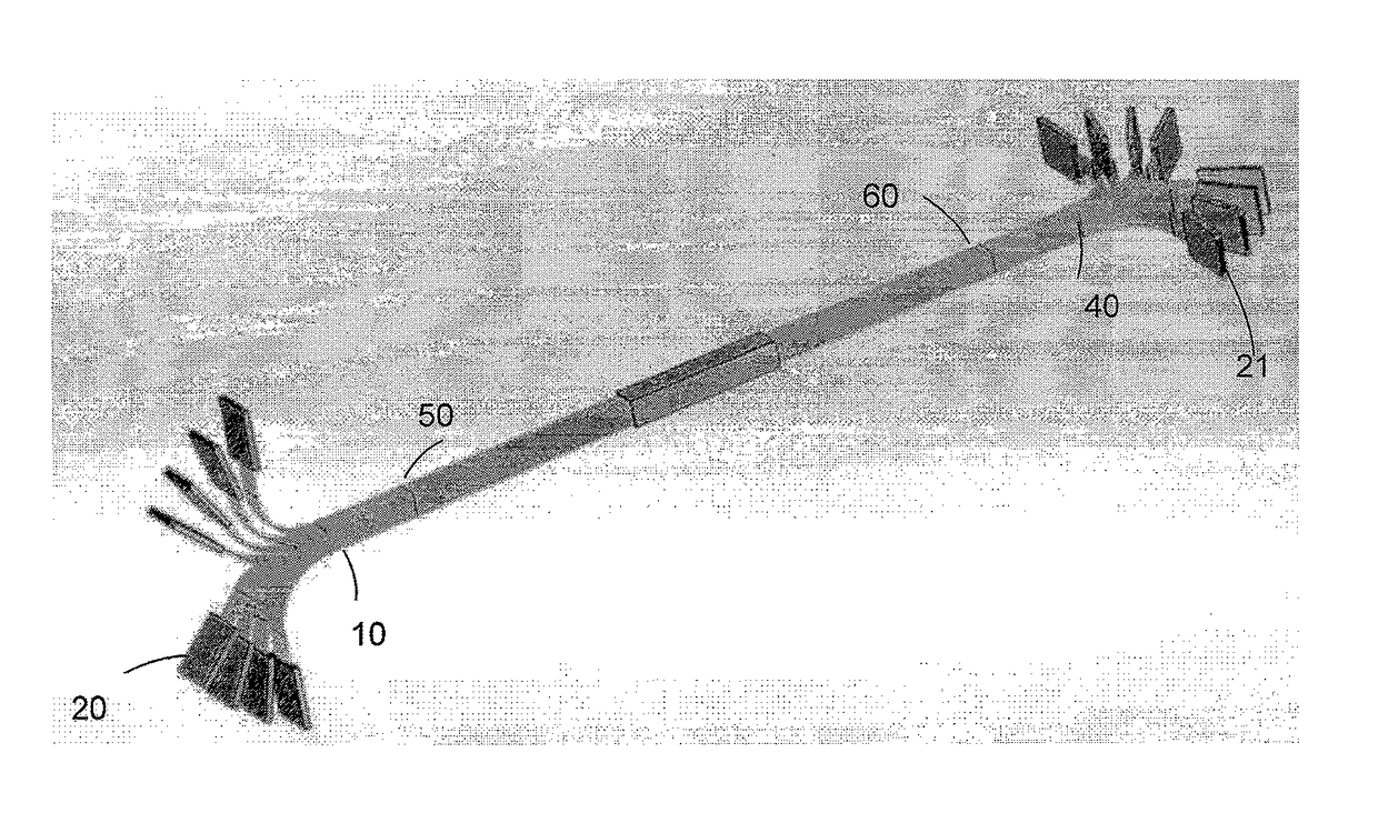
[0021]The method disclosed herein is based on an observation that an N by M matrix of fiber ends may have connectors attached either horizontally or vertically with respect to the instant position of the matrix. In other words, the N×M arrangement of fibers that has N rows and M columns may be connectorized with N connectors or with M connectors. The inventor has realized that, if the N×M arrangement of fibers is maintained, using M connectors at one end of the cable and N connectors—at the other end will form an interconnect device without actual shuffling of fibers, but only regrouping the fibers differently at different ends of the cable.

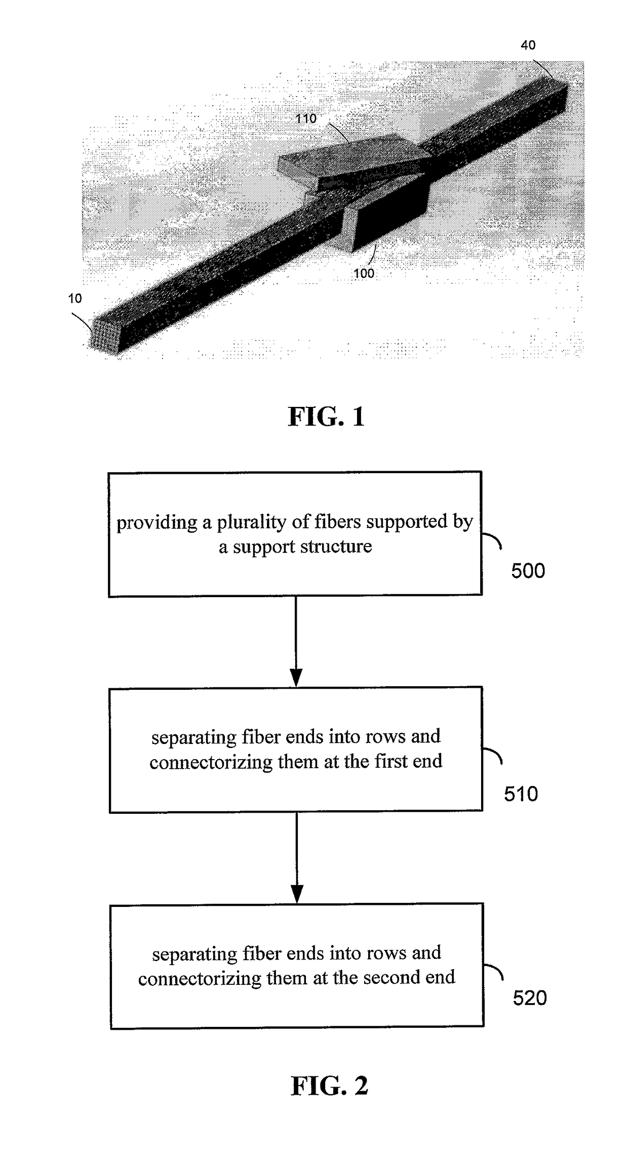
[0022]FIG. 1 illustrates a convenient way of arranging fibers by placing then in a Π-shaped support 100 with an optional lid 110, The rectangular cross-section of the support 100 helps to arrange the fibers into an N×M arrangement. With the sufficient length of the support, the fibers are kept parallel to each other within the support and fiber e...


PUM


Abstract

A method of manufacturing an optical cable includes providing a plurality of fibers supported by a support structure, wherein, positions of the plurality of fibers in a reference cross-section form N rows extending in a first direction and M rows extending in a second direction different from the first direction. The method includes separating fiber ends at the first cable end into N rows and connectorizing them with N connectors. The method also includes separating fiber ends at the second cable end into M rows and connectorizing them with M connectors.

Description

CROSS-REFERENCE TO RELATED APPLICATIONS[0001]The present application claims priority from U.S. Patent Application No. 62 / 377,038 filed Aug. 19, 2016, and U.S. patent application Ser. No. 15 / 494,598 filed Apr. 24, 2017, which are incorporated herein by reference for all purposes.TECHNICAL FIELD[0002]The present disclosure relates generally to optical cables and, more particularly, to regroup cables and methods for making thereof.BACKGROUND OF THE INVENTION[0003]The modern telecommunication systems often include optical fiber networks, and thus require a variety of equipment, including devices for multiplexing, demultiplexing, and switching of optical signals. The switching may be implemented in the electronic domain; however, the electronic circuits limit the maximum bandwidth of the signal. Therefore, it is desirable to use transparent, all-optical devices.[0004]One particular problem associated with optical switching relates to an N×M interconnect, wherein signals of N devices are ...

Claims


Application Information

Patent Timeline
IPC IPC(8): G02B6/36G02B6/44G02B6/38
CPCG02B6/4471G02B6/3672G02B6/3668G02B6/3885G02B6/3893G02B6/4479G02B6/4439
Inventor QIAO, LIJIE
Owner ACCELINK TECHNOLOGIES CO LTD
Why Eureka
Try Eureka