Motion compensation in photopletysmography-based heart rate monitoring

a heart rate monitoring and motion compensation technology, applied in the field of photopletysmography (ppg)based heart rate determination, can solve the problems of noise corruption and unreliable heart rate determination

Active Publication Date: 2017-12-12
STMICROELECTRONICS SRL
View PDF2 Cites 0 Cited by
  • Summary
  • Abstract
  • Description
  • Claims
  • Application Information

AI Technical Summary

Benefits of technology

[0008]The method may further include: scaling the second reflected signal by a reciprocal of an amplitude adapting coefficient before obtaining the heart rate signal as the difference between the first reflected signal and the second reflected signal using the second reflected signal scaled by the reciprocal of the amplitude adapting coefficient. The amplitude adapting coefficient may be a divisor of the second reflected signal that minimizes a difference in energy between the first reflected signal and the quotient of the second reflected signal and the amplitude adapting coefficient. The method may further include: time shifting the second reflected signal prior to obtaining the heart rate signal using the time shifted second reflected signal. The second reflected signal may be shifted by a time index corresponding to a maximum cross-correlation value between the first reflected signal and the second reflected signal. The method may further include: filtering the first and second reflected signals; and de-trending the first and second reflected signals.

Problems solved by technology

The noise corrupts a heart rate signal detected by the heart rate measurement device using PPG techniques.
Further, the noise makes heart rate determination unreliable.

Method used


Image

  • Motion compensation in photopletysmography-based heart rate monitoring
  • Motion compensation in photopletysmography-based heart rate monitoring
  • Motion compensation in photopletysmography-based heart rate monitoring

Examples


Embodiment Construction

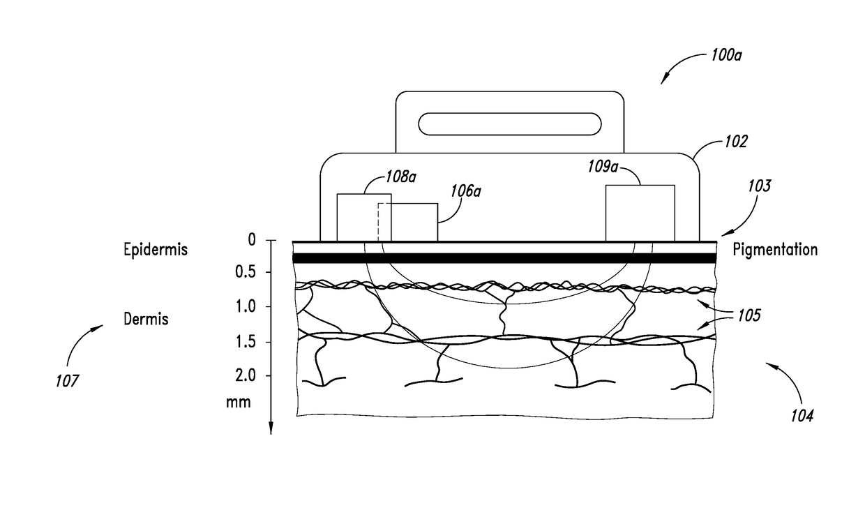
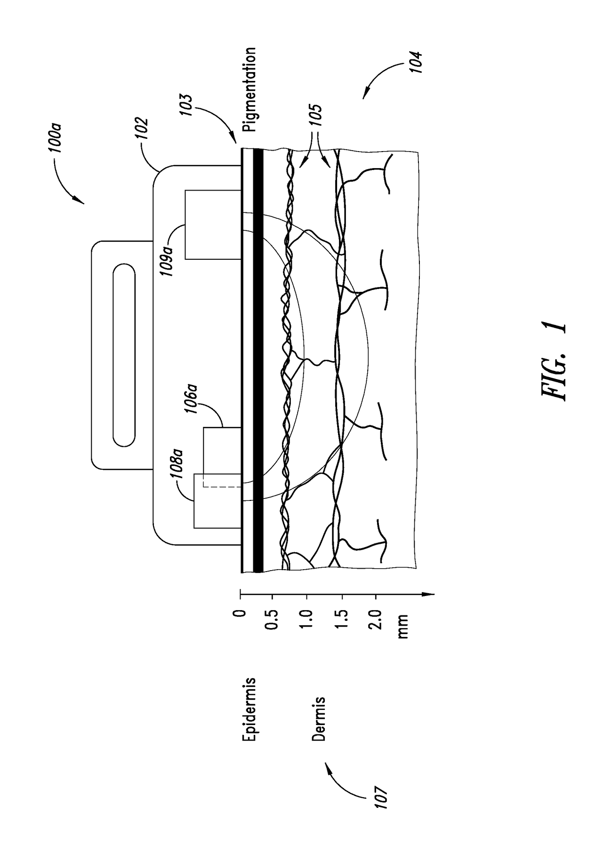
[0018]FIG. 1 shows a cross-sectional view of heart rate measurement device 100a positioned near the skin 103 of a biological body 104. The heart rate measurement device 100a is used to measure the heart rate of the biological body 104 using photopletysmography (PPG). The heart rate measurement device 100a includes a probe 102 having a first light source 106a, a second light source 108a and a photodetector 109a. The probe 102 is positioned near the skin 103 of the biological body 104 (and may, for example, be in contact with the skin 103). Light emanating from the first light source 106a and the second light source 108a is captured by the photodetector 109a after having at least partially penetrated the biological body 104 and been reflected by the biological body 104.

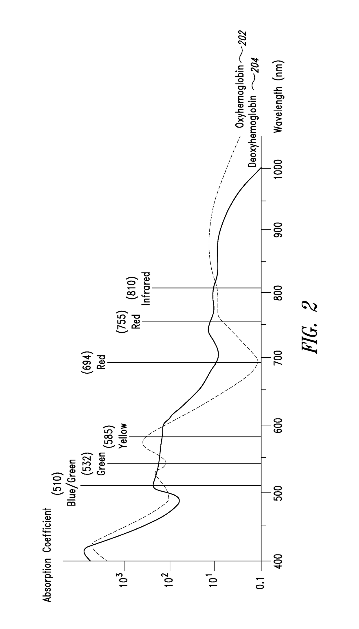
[0019]PPG is a non-invasive technique for heart rate measurement and detection. PPG relies on the principle that blood components, such as oxyhemoglobin and deoxyhemoglobin, reflect back light having certain wavelengths...


PUM


Abstract

A method and apparatus for determining a heart rate of a biological body are disclosed. In the method and apparatus, light having a first wavelength and light having a second wavelength are emitted at the biological body. The first wavelength is associated with a first absorption coefficient for blood components and the second wavelength is associated with a second absorption coefficient for the blood components that is less than the first absorption coefficient. A first reflected signal is captured as a result of the light having the first wavelength being reflected from the biological body and a second reflected signal is captured as a result of the light having the second wavelength being reflected from the biological body. A heart rate signal is obtained based on the first and second reflected signals. A heart rate of the biological body is determined based on the heart rate signal.

Description

BACKGROUND[0001]Technical Field[0002]The present disclosure relates to photopletysmography (PPG)-based heart rate determination under motion conditions. In particular, the present disclosure relates to a device that compensates motion artifacts introduced in a PPG signal.[0003]Description of the Related Art[0004]PPG-based heart rate monitoring and determination is sensitive to noise artifacts. The noise artifacts can be introduced as a result of movement of a biological body or a heart rate measurement device used to perform the heart rate measurement. The noise corrupts a heart rate signal detected by the heart rate measurement device using PPG techniques. Further, the noise makes heart rate determination unreliable.BRIEF SUMMARY[0005]A device may be summarized as including: a first light source configured to emit light having a first wavelength at a biological body, the first wavelength being associated with a first absorption coefficient for blood components; a second light sourc...

Claims


Application Information

Patent Timeline
Patent Type & Authority Patents(United States)
IPC IPC(8): A61B5/00A61B5/024
CPCA61B5/7282A61B5/02427A61B5/742A61B5/7246A61B5/7225A61B5/721A61B5/7214
Inventor GUMIERO, ALESSANDRO
Owner STMICROELECTRONICS SRL
Why Eureka
Try Eureka