Photoresist film with adhesive layer and microspheres

a technology of adhesive layer and film, applied in the field of photoresist film, can solve the problems of difficult repositioning of film, weakening of film, and the inability to engrave as many details into an object, and achieve the effect of manufacturing thinner films

Active Publication Date: 2017-12-19
RAYZIST PHOTOMASK
View PDF6 Cites 0 Cited by
  • Summary
  • Abstract
  • Description
  • Claims
  • Application Information

AI Technical Summary

Benefits of technology

[0015]An advantage of the present invention is that the film is very easy to remove and reattach to in a different location on the object prior to pressure being applied, yet after pressure is applied, the attachment is strong enough to not move during the engraving process. This repositionable feature is accomplished through a unique adhesive layer.
[0016]Another advantage of the present invention is that the film sticks very well, and thus is configured to attach to a broad range of surfaces given the repositionable nature of the film, which one might expect only attached to polished surfaces such as glass, and not other surfaces such as rocks, flagstone, etc.
[0017]A further advantage of the present invention is that the film is very strong and thus can be manufactured thinner without risking the engraving process cutting through the non-design portions of the film. A thinner film allows more details to be engraved in the object. This strong yet thin feature is accomplished through microspheres, which are air bubbles, in the photoresist layer.

Problems solved by technology

A problem with conventional photoresist films is the difficulty repositioning the film to a surface of an object such that the design can be observed on the object, and such that the precise arrangement can be confirmed, prior to adhesion.
Another problem with conventional photoresist films is achieving a thin width but without weakening the film.
However, a thicker film unfortunately does not allow as many details to be engraved into an object, compared to a thinner film.
Since Vanlseghem's adhesive has a high degree of tack, it cannot be easily shifted, rotated, moved, or otherwise repositioned prior to applying pressure.
However, Shigematsu is unrelated and not relevant to photoresist films, and instead is for a heat pack or body warmer, which is unrelated to engraving.

Method used


Image

  • Photoresist film with adhesive layer and microspheres
  • Photoresist film with adhesive layer and microspheres
  • Photoresist film with adhesive layer and microspheres

Examples


Embodiment Construction

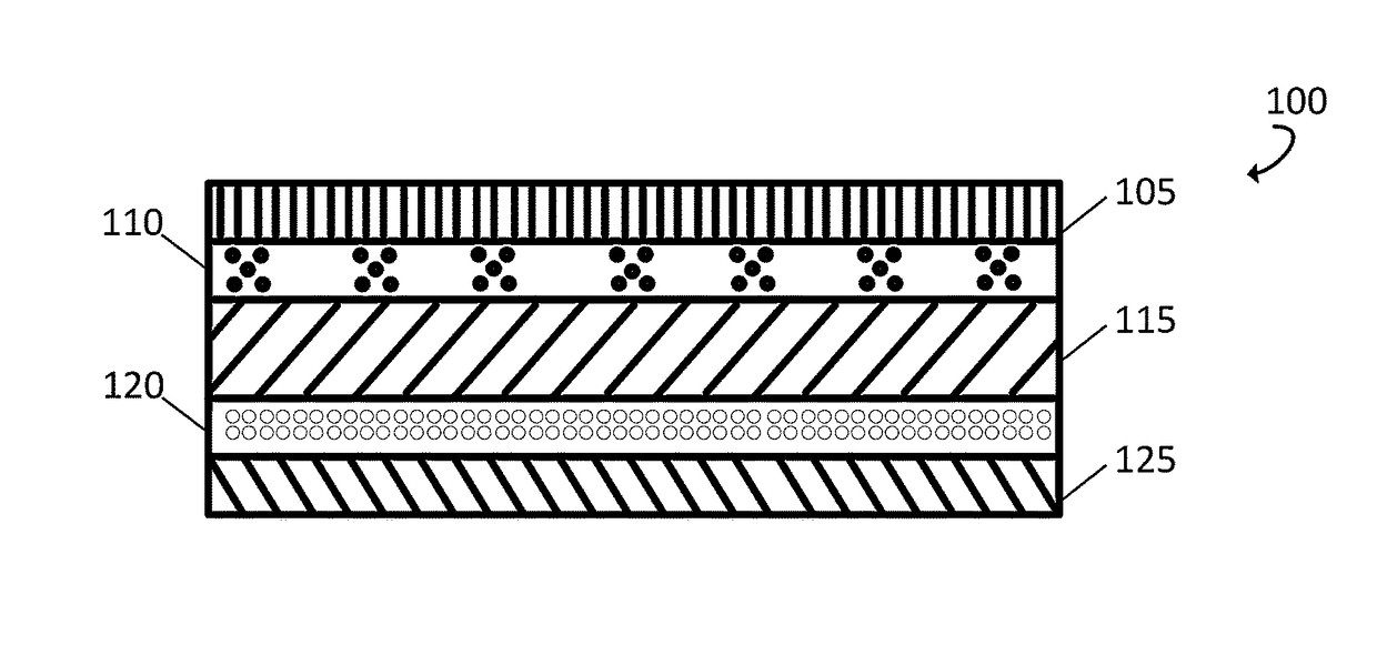
[0025]Further features and advantages of the invention, as well as the structure and operation of various embodiments of the invention, are described in detail below with reference to the accompanying FIGS. 1-5, wherein like reference numerals refer to like elements.

[0026]Although the invention is at times described in the context of a particular object, such as glass, one of ordinary skill in the art readily appreciates that the present invention can be implemented with other engraving surfaces. Additionally, although the invention is described as a five layer film, one of ordinary skill in the art readily appreciates that the present invention can be implemented with more or less layers without departing from the spirit of the invention. For example, it is common for a film to have more than one film / photoresist layer.

[0027]For the purposes of the present application, the term and process of “engraving” is used to represent similar processes, and as such is defined to include at l...


PUM

PropertyMeasurementUnit
thicknessaaaaaaaaaa
thicknessaaaaaaaaaa
thicknessaaaaaaaaaa

Abstract

The present invention provides, in at least one embodiment, a film and method for engraving objects. The film includes an adhesive layer configured to allow the film to be easily repositionable on the surface of an object. For example, the film can be shifted, rotated, or moved prior to pressure being applied and before the engraving. Additionally, the photoresist layer includes microspheres comprising small pockets of air which strengthen the photoresist layer by bouncing the engraving blast away and allow the photoresist layer to advantageously be designed thinner.

Description

BACKGROUND OF THE INVENTION[0001]1. Field of Invention[0002]The invention relates generally to a photoresist film for engraving, and more particularly, to easily repositioning the film prior to pressure being applied and before the engraving.[0003]2. Description of Related Art[0004]Engraving is the practice of incising a design into a hard, usually, but not limited to flat surface, by cutting grooves into it. Common surfaces to engrave include glass, wood, stone or any other hard surface that will abrade away.[0005]Traditional engraving continues to be practiced today by goldsmiths, glass engravers, monument makers, gunsmiths and others, while modern industrial techniques such as laser engraving have many important applications as well. Laser engraving is the practice of using a laser to engrave or mark an object, and it does not use tools which contact the engraving surface and it does not wear out.[0006]Engraving applies a photoresist to the surface to be engraved to create a mask...

Claims


Application Information

Patent Timeline
Patent Type & Authority Patents(United States)
IPC IPC(8): B32B27/00C09J7/02C08K7/22C09D1/00C09J7/29
CPCB32B27/00C09J7/0296C03C2218/34C08K7/22C09D1/00Y10T428/24612C09J2205/106C09J2205/11C09J2431/00Y10T156/10Y10T428/24496C09J2201/606C09J7/29C09J2301/412C09J2301/41C09J2301/302
Inventor WILLIS, RANDYWILLIS, JOSH
Owner RAYZIST PHOTOMASK
Why Eureka
Try Eureka