Frameless supplemental window for fenestration

a frameless, supplemental window technology, applied in the field of supplemental windows, can solve the problems of preventing more widespread and effective utilization, limiting the application of supplemental windows, and difficult manufacturing of size customization, so as to maximize thermal insulation properties and mechanical stability, and add rigidity and strength

Active Publication Date: 2017-12-19
WEXENERGY
View PDF286 Cites 5 Cited by
  • Summary
  • Abstract
  • Description
  • Claims
  • Application Information

AI Technical Summary

Benefits of technology

[0007]The present invention is a frameless supplemental window for fenestration suitable for use with existing windows. The supplemental window, in one embodiment, comprises sheet material with an edging seal around it. In some embodiments, corner braces add rigidity and strength to corners in several embodiments. In other embodiments, corner braces provide a portion of the corner closure of the edging seal. An attachment mechanism secured either to the sheet material or the edging functions to fasten and / or seal the supplemental window to an existing window. The edging functions to substantially enclose (i.e. trap) a volume of air between the window pane and the plastic sheet material. The supplemental window is configured such that the layer of trapped air is of an optimum thickness within a preferred range of 0.15 to 0.75 inches to maximize thermal insulation properties and mechanical stability of the supplemental window when mounted.
[0008]Several advantages of the supplemental window include (1) frameless designs that significantly reduce material cost; (2) decreased heat transfer through the window area; (3) retaining visual transparency through the window; (4) having a reduced cost of manufacture; and (5) designable so as to not impede the operability of the existing window or associated window treatments.
[0009]The aesthetics of the fenestration during and after use of the supplemental window can be maintained. This relates to maintaining the appearance of the interior view of the fenestration and its immediate surrounding as well as the ability to see through the fenestration when desired. Also, it relates to the ability to return the fenestration to its original state when the supplemental element is not being used without the need to repair mounting areas.
[0010]Operability of the fenestration and associated treatment during use of the supplemental window can be maintained without the need to demount the supplemental window. Since the fenestration is often designed for opening and closing, it is beneficial to maintain this capability while the supplemental window is in place. This would allow for temporarily bringing fresh air into the space adjacent to the fenestration. This can be particularly useful during periods of moderate temperatures within a heating or cooling season.
[0011]The supplemental window also provides the ability to gain energy efficiency improvement during both heating and cooling seasons. The advent of spectrally selective, infrared reflective and low-emissivity coatings or laminates for window films provides for additional energy savings. Incorporation of such coatings or films in the sheet and / or edging provides an opportunity for combining these additional energy saving technologies with the insulating properties provided by the substantially enclosed air volume provided by the present invention. Optimal placement of such films, however, requires the ability to move such films to either keep heat in during the heating season or keep heat out in the cooling season.

Problems solved by technology

While these approaches have shown considerable improvement in building energy efficiency, significant problems prevent more widespread and effective utilization.
Several problems exist in the approaches to minimizing heat transfer through fenestration.
Supplemental window elements known in the art either require the end user to customize supplemental window elements to the dimensions of each window at the site of installation or are designed in ways that make size customization difficult in manufacturing.
In addition, such window films often must be mounted in such a way that inhibits the operability of non-fixed windows.
Other window films, such as tints, infrared or ultraviolet reflective, or low-e films, generally adhere directly to the window pane and do not allow for simultaneous formation of an insulating layer.

Method used


Image

  • Frameless supplemental window for fenestration
  • Frameless supplemental window for fenestration
  • Frameless supplemental window for fenestration

Examples


Embodiment Construction

[0056]The invention is described below, with reference to detailed illustrative embodiments. It will be apparent that the invention can be embodied in a wide variety of forms, some of which may be quite different from those of the disclosed embodiments. Consequently, the specific structural and functional details disclosed herein are merely representative and do not limit the scope of the invention.

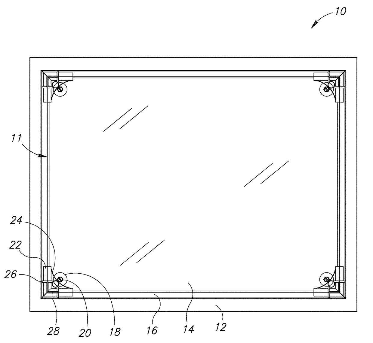
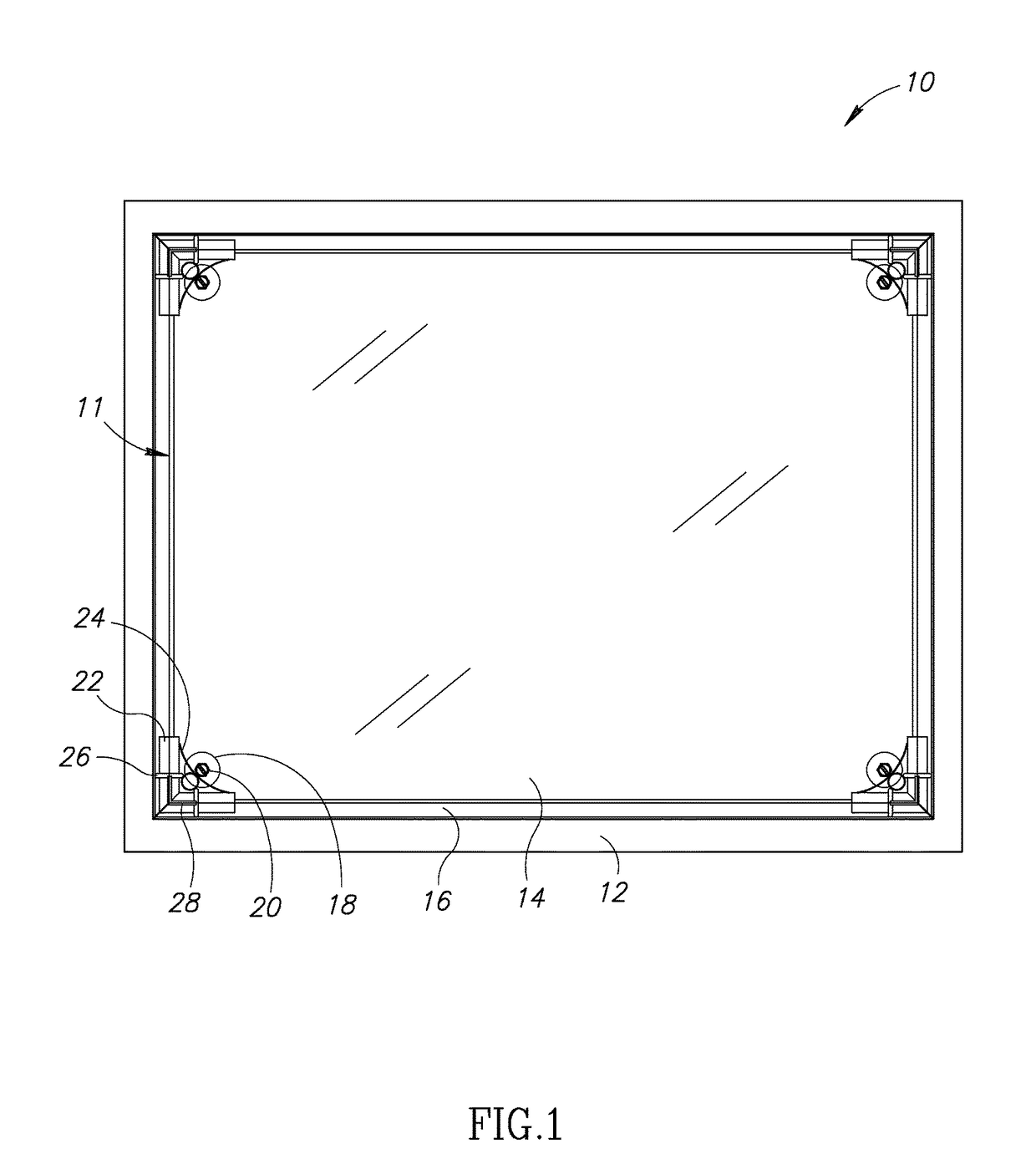
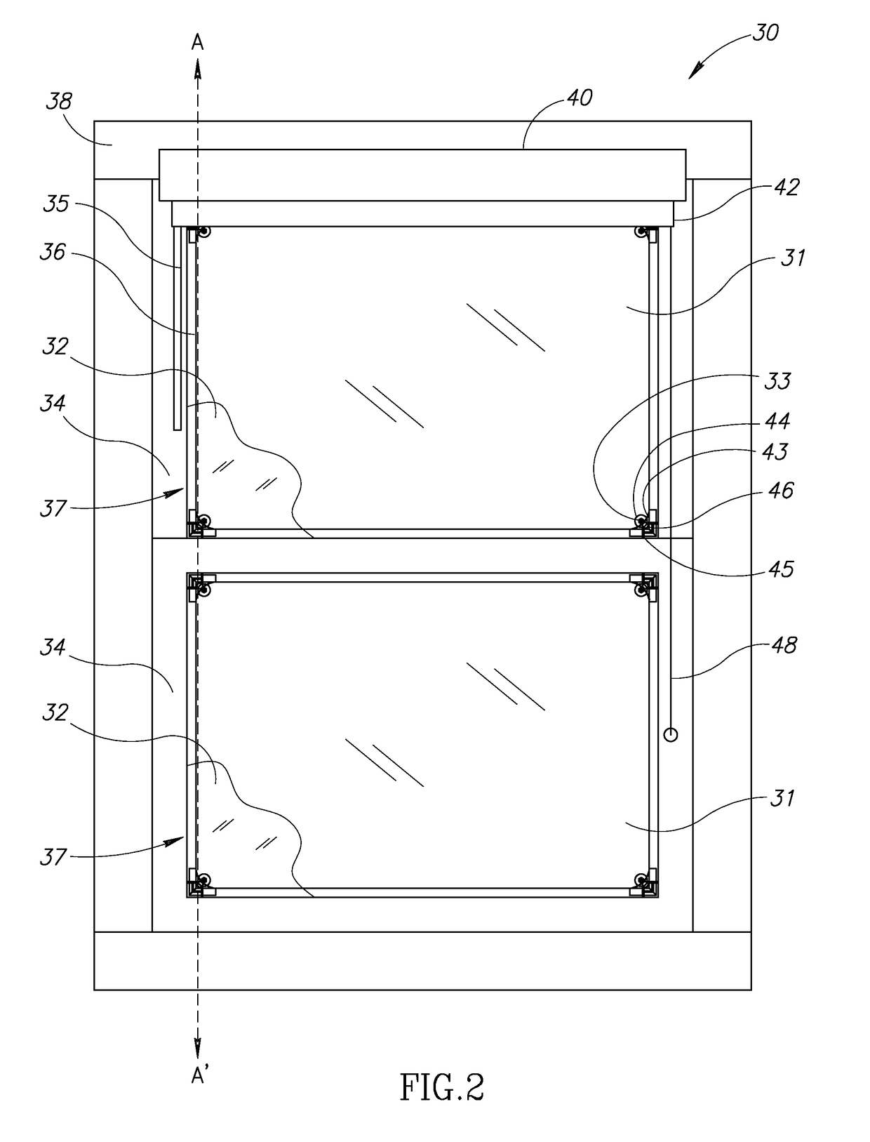
[0057]The present invention provides for several embodiments for mounting of sheet material in or over fenestration and substantially enclosing a volume of gas in or adjacent to the fenestration. The term “frameless supplemental window” in the present invention refers to a supplemental window that lacks a substantially rigid or non-flexible structure surrounding an area that is approximately the same size as the window pane on which the supplemental window is to be mounted.

[0058]In the present invention, in one embodiment, sheet material, a spacer or post of predetermined dimension perpen...


PUM


Abstract

A novel and useful frameless supplemental window for fenestration suitable for use with existing windows. The supplemental window, in one embodiment, comprises plastic sheet material with bullnose edging around it. Corner braces add rigidity and strength to corners in several embodiments. An attachment mechanism secured either to the sheet material or the bullnose edge functions to fasten and / or seal the supplemental window to an existing window. The bullnose edging functions to substantially enclose (i.e. trap) a volume of air between the window pane and the plastic sheet material. The supplemental window is configured such that the layer of trapped air is of an optimum thickness within a preferred range of 0.15 to 0.75 inches to maximize thermal insulation properties of the supplemental window.

Description

REFERENCE TO PRIORITY APPLICATION[0001]This application is a continuation-in-part of U.S. application Ser. No. 14 / 315,503, filed Jun. 26, 2014, entitled “Supplemental Window For Fenestration,” which is a continuation-in-part of U.S. application Ser. No. 13 / 735,449, filed Jan. 7, 2013, now U.S. Pat. No. 8,923,650, entitled “System and Method of Measuring Distances Related to an Object,” both of which are incorporated herein by reference in their entirety.FIELD OF THE INVENTION[0002]The present invention relates generally to fenestration and in particular to a frameless supplemental window and related method of construction and mounting for use with existing windows.BACKGROUND OF THE INVENTION[0003]In recognition of the ecological and cost impact of fossil fuels and other conventional energy sources, significant effort has been expended in developing methods for more efficient use of such energy sources. An important area of energy use for which greater energy efficiency is needed is ...

Claims


Application Information

Patent Timeline
Patent Type & Authority Patents(United States)
IPC IPC(8): E06B3/28E06B3/26E06B1/34E06B3/30E06B9/24
CPCE06B3/28E06B1/34E06B9/24E06B3/285E06B3/30E06B3/26
Inventor WEXLER, RONALD MYRON
Owner WEXENERGY
Why Eureka
Try Eureka