Tool attachment for a handheld machine tool

a handheld machine tool and tool technology, applied in the field of tool attachments, can solve the problems of loss of convenience for the user of the tool attachment, and achieve the effect of convenient, quick and easy use for the user

Active Publication Date: 2017-12-26
ROBERT BOSCH GMBH
View PDF9 Cites 1 Cited by
  • Summary
  • Abstract
  • Description
  • Claims
  • Application Information

AI Technical Summary

Benefits of technology

[0005]It is therefore one object of the present invention to provide a new tool attachment that is able to be fastened in a specified angular position on a handheld machine tool, and in which a change in the specified angular position is able to take place in a manner that is uncomplicated, rapid and convenient for a user.
[0006]This object may be attained by a tool attachment having an attachment housing, on which is situated a fastening interface for fastening to an handheld machine tool. The fastening interface has an angular position setting unit for setting a specified angular position of the tool attachment on the handheld machine tool, and is equipped with a locking unit which, in a locked state, locks the tool attachment for operation on the handheld machine tool in the specified angular position, and in the unlocked state, makes possible drawing the tool attachment away from the handheld machine tool. The angular position setting unit is operable in the locked state of the locking unit, to make possible a change in the specified angular position.
[0007]Consequently, the present invention makes possible providing a tool attachment in which, by the operation of an angular position setting unit in the locked state of the locking unit, a change in the respective angular position may be achieved. Thus, one may do without the operation of the locking unit before and after operating the angular position setting unit, so that the change of the respective angular position may be sped up in a simple manner, and the design is thus more convenient for a user of the tool attachment.

Problems solved by technology

It is believed that a disadvantage in the related art is that the handling of such a tool attachment is cumbersome and complicated, and may thus lead to a loss in convenience for a user of the tool attachment.

Method used


Image

  • Tool attachment for a handheld machine tool
  • Tool attachment for a handheld machine tool
  • Tool attachment for a handheld machine tool

Examples


Embodiment Construction

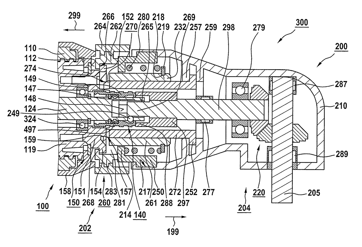
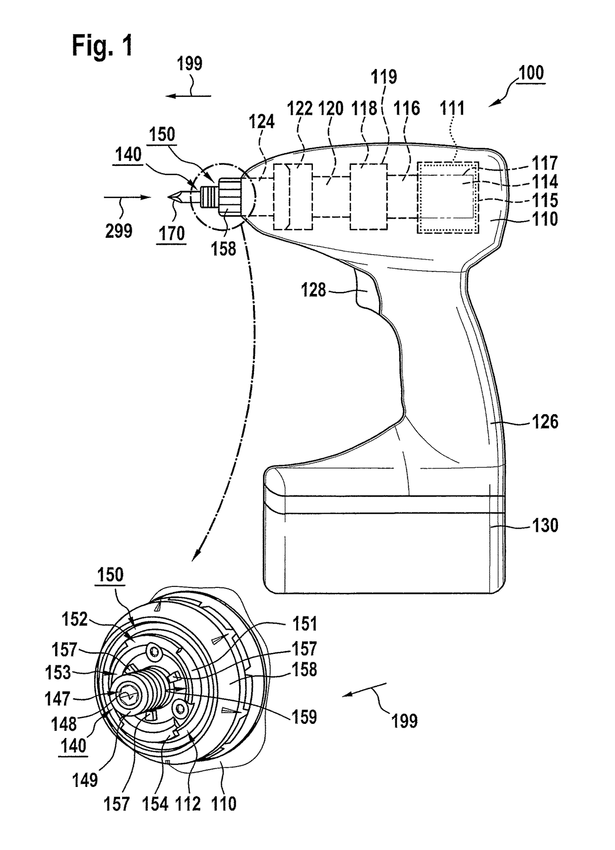
[0040]FIG. 1 shows an handheld machine tool 100 equipped with a tool holding fixture 140, which has a housing 110 having a handle 126. According to one specific embodiment, handheld machine tool 100 is able to be connected, mechanically and electrically, to a rechargeable battery pack 130 for a power supply that is network-independent.

[0041]Handheld machine tool 100 is configured as a battery-driven rotary blow screwdriver, by way of example. It should be pointed out, however, that the present invention is not limited to battery-driven rotary blow screwdrivers, but rather that it can find application in different types of handheld machine tools, which have a tool holding fixture corresponding to tool holding fixture 140, independently of whether the handheld machine tool is able to be operated electrically, i.e. network-independently using battery pack 130 or network-dependently, and / or non-electrically.

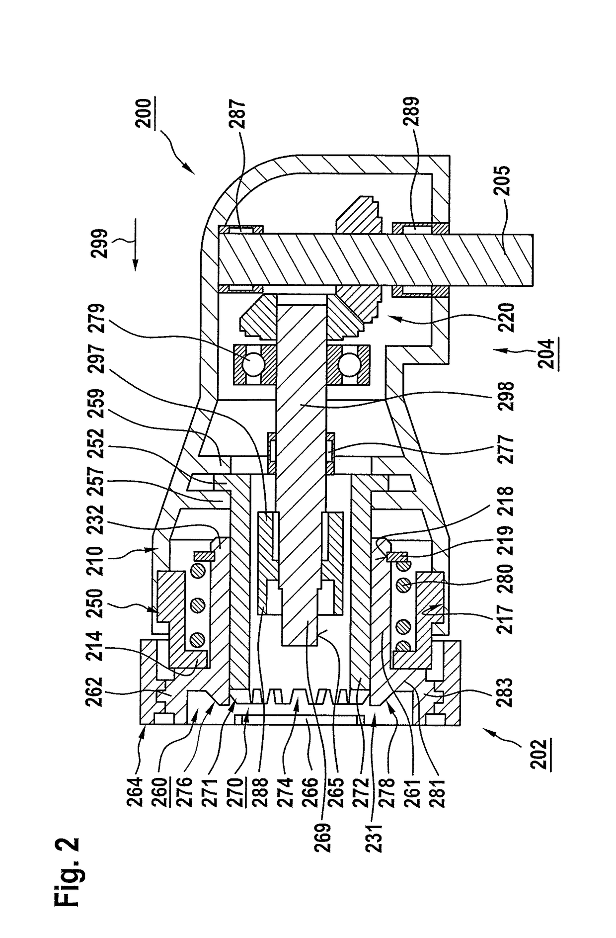
[0042]In housing 110, there are situated an electric drive motor 114 supplied wi...


PUM


Abstract

In a tool attachment having an attachment housing on which a fastening interface is situated for fastening to an handheld machine tool, the fastening interface having an angular position setting unit for setting a specified angular position of the tool attachment on the handheld machine tool, and being equipped with a locking unit which, in a locked state, locks the tool attachment for operation on the handheld machine tool in the specified angular position, and, in the unlocked state, makes possible drawing the tool attachment away from the handheld machine tool, the angular position setting unit is operable in the locked state of the locking unit, to enable a change in the specified angular position.

Description

RELATED APPLICATION INFORMATION[0001]The present application claims priority to and the benefit of German patent application no. 10 2012 220 910.7, which was filed in Germany on Nov. 15, 2012, and German patent application no. 10 2013 213 806.7, which was filed in Germany on Jul. 15, 2013, the disclosures of both of which are incorporated herein by reference.FIELD OF THE INVENTION[0002]The present invention relates to a tool attachment having an attachment housing, at which a fastening interface is situated for fastening to a handheld machine tool, the fastening interface having an angular position setting unit for setting a specified angular position of the tool attachment on the handheld machine tool, and is equipped with a locking unit which, in a locked state, locks the tool attachment for operation on the handheld machine tool in the specified angular position and in the unlocked state, makes possible drawing the tool attachment away from the handheld machine tool.BACKGROUND IN...

Claims


Application Information

Patent Timeline
Patent Type & Authority Patents(United States)
IPC IPC(8): B25F5/00B25F3/00B23B31/02B25B23/00
CPCB25F5/00B23B31/026B25F3/00B25B23/0007Y10T403/32418
Inventor TUSSING, TORSTEN
Owner ROBERT BOSCH GMBH
Why Eureka
Try Eureka