
Control device for controlling electric vehicle

a technology for controlling devices and electric vehicles, applied in the direction of process and machine control, braking systems, instruments, etc., can solve the problems of inability to keep the electric vehicle at the stopping state, wasteful consumption of energy (electric power) for generating the creep torque during the stopping of the vehicle, and electric vehicle backward movement, etc., to suppress the electric vehicle stopped, control the creep torque suitably, and suppress the effect of energy consumption

Active Publication Date: 2018-01-09
MITSUBISHI MOTORS CORP
View PDF4 Cites 2 Cited by
  • Summary
  • Abstract
  • Description
  • Claims
  • Application Information

AI Technical Summary

Benefits of technology

The control device for electric vehicles described in this patent text can manage the braking system to prevent energy consumption and prevent the vehicle from moving backward. Specifically, the device interlinks the brake pedal depression with the decision to suppress the creep torque, which is the force that keeps the vehicle in a stable position when it has stopped. This allows for more efficient braking and better control of the vehicle's movement. Additionally, the device takes into account the maximum braking force during stopping to calculate the appropriate amount of creep torque needed to prevent movement. Overall, this technology helps to save energy and improve the performance of electric vehicles.

Problems solved by technology

Therefore, energy (electric power) for generating the creep torque during stopping of the vehicle is wastefully consumed.
However, as to the electric vehicle in which the creep torque is reduced to zero during stopping of the vehicle, as described in Japanese Patent No. 4127310, there is a fear that the electric vehicle may move backward when, for example, depression of the brake pedal is too shallow during stopping of the vehicle on an uphill road, to make it impossible to keep the electric vehicle at the stopping state.
Such a problem may occur even in a state in which the brake pedal has been depressed.
Particularly, such a problem is apt to occur when the brake auto-hold control in which the brake pedal has not been depressed is in execution.

Method used


Image

  • Control device for controlling electric vehicle
  • Control device for controlling electric vehicle
  • Control device for controlling electric vehicle

Examples


Embodiment Construction

[0021]An embodiment of the invention will be described below in detail with reference to the drawings.

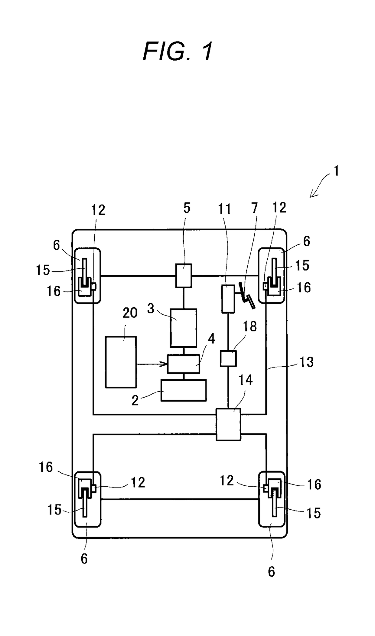
[0022]First, an overall configuration of an electric vehicle according to the embodiment will be described. As shown in FIG. 1, the electric vehicle 1 according to the embodiment is an electric vehicle (EV) provided with a battery 2 and a traction motor (electric motor) 3. The battery 2 is a rechargeable battery. The traction motor 3 serves as a driving source operated by electric power supplied from the battery 2. The battery 2 and the traction motor 3 are connected to each other through an inverter 4. For example, the traction motor 3 is coupled to wheels (front wheels which are driving wheels in the embodiment) 6 through a transmission system 5 including a not-shown automatic transmission etc.

[0023]In addition, the electric vehicle 1 is provided with a braking device for applying braking force to each wheel 6. The braking device is a so-called hydraulic braking device which is pr...


PUM


Abstract

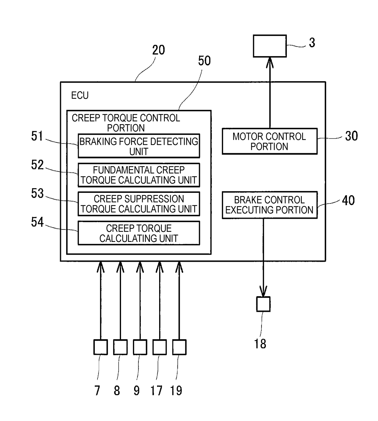
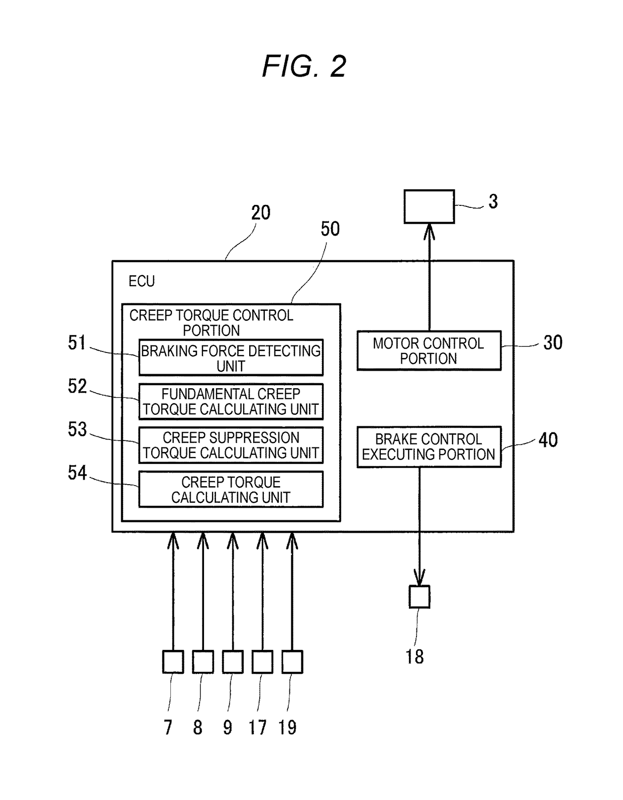
A control device for controlling an electric vehicle includes a driving source that rotates wheels, a braking device that applies braking force to the wheels, a creep torque control portion that controls magnitude of creep torque to be applied to the wheels, wherein the creep torque control portion includes a braking force detecting unit that detects the braking force applied by the braking device, a fundamental creep torque calculating unit that calculates fundamental creep torque corresponding to vehicle speed, a creep suppression torque calculating unit that calculates creep suppression torque smaller than the fundamental creep torque based on a result of the detection of the braking force detecting unit and a creep torque calculating unit that calculate the creep torque by subtracting the creep suppression torque from the fundamental creep torque.

Description

CROSS REFERENCE TO RELATED APPLICATION[0001]This application is based on Japanese Patent Application No. 2015-250561 filed on Dec. 22, 2015, the contents of which are incorporated herein by reference.BACKGROUND OF THE INVENTION[0002]1. Technical Field[0003]The present invention relates to a control device for controlling an electric vehicle which is provided with a driving source such as a traction motor (electric motor).[0004]2. Related Art[0005]For example, electric vehicles such as electric vehicles or hybrid vehicles heretofore have traction motors (electric motors) etc. provided as driving sources. According to a configuration of one of the traction motors provided in the electric vehicles, the traction motor generates plus-side driving force (torque) for making the electric vehicle travel by use of electric power from a battery, and on the other hand, the traction motor is operated as a power generator during deceleration etc. to generate minus-side regenerative force (torque)...

Claims


Application Information

Patent Timeline
Patent Type & Authority Patents(United States)
IPC IPC(8): B60R22/00G06F7/00G05D3/00G05D1/00E05F15/00B60W10/18
CPCB60W10/18B60W2710/182B60L15/2009B60L15/2063B60W10/08B60W10/184B60W30/18063B60W30/18109B60L2240/423B60L2240/12B60W2540/12B60W2510/182B60W2520/10B60T7/122B60T2201/06B60L2260/10Y02T10/72Y02T10/64
Inventor SASAKI, YUSUKEIKOMA, NORIHIKOKAMACHI, MAKOTOTOMITA, YOSHINORISHIMIZU, RYO
Owner MITSUBISHI MOTORS CORP
Learn More